2.2-5 Connectors
Compact, low-PIM RF connectors ideal for small-cell, DAS and 5G infrastructure
Overview
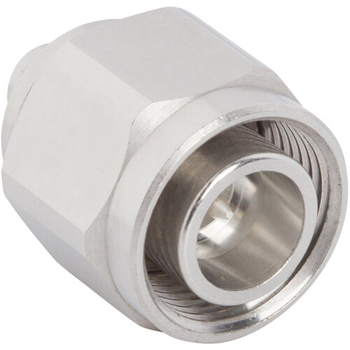
Amphenol RF’s 2.2‑5 connector family delivers a 53% reduction in size compared to 4.3‑10 connectors while supporting the same robust performance. Designed for high-frequency RF systems, these lightweight connectors accommodate thick, low-loss cables up to ½″ and maintain excellent passive intermodulation (PIM) performance—essential for demanding wireless and broadcast deployments. IP68-rated when mated, they’re engineered to perform reliably in both indoor and outdoor environments.
This series is optimized for quick assembly through both push‑pull blind-mate and threaded coupling options, enhancing installation flexibility. With support for DC–20 GHz and PIM as low as –166 dBc, 2.2‑5 connectors are ideal for high-density RF applications, including small cells, in-building systems and mobile base stations.
Features and Benefits
- Ultra-compact footprint: 53% smaller than 4.3‑10 connectors, ideal for space-constrained designs
- Low‑PIM performance: Achieves −166 dBc at 2 × 20 W, preserving network signal quality
- High-frequency range: Operates from DC to 20 GHz when terminated with the right cable
- Installation flexibility: Offers push‑pull blind-mate and threaded coupling mechanisms
- Rugged reliability: IP68 sealed in mated condition for outdoor and harsh environments.
Key Technical Details
- Supports ½″ diameter cables, including conformable and semi-rigid types
- DC–20 GHz frequency range (cable-dependent)
- Voltage rating: 500 VRMS continuous; dielectric withstanding voltage of 1500 VRMS
- VSWR: ~1.025 (DC–3 GHz), ~1.032 (3–6 GHz), cable/color-dependent
- Power handling: 250 W at 2 GHz, 40 °C; Intermodulation (PIM): –166 dBc @ 2 × 20 W
Applications
- Small-cell and 5G networks – compact, high-performance connector for dense deployments
- Distributed antenna systems (DAS) – low-PIM connectors for high-speed signal distribution
- In-building wireless – reliable RF interface for corporate, healthcare and campus systems
- Low-power base stations – rugged design tolerates environmental exposure
- Test and measurement – high-frequency, low-reflection interface for lab and field use
Browse our complete range of 2.2‑5 connectors—including straight, right-angle and panel-mount variants. If you require custom cable assembly, impedance variation, or specialized mounting options, contact our experts to explore tailored design solutions.
Specifications
2.2-5 Connector
Electrical
| Impedance | 50 Ohm |
| Frequency Range | DC - 20 GHz |
| Voltage Rating | 500 Volts RMS Continuous |
| Dielectric Withstanding Voltage | 1500 VRMS Min |
| VSWR |
|
|
Interface
|
|
|
DC - 3 GHz
|
1.025 (-38 dB) Typ |
|
3 - 6 GHz
|
1.032 (-36 dB) Typ |
|
Cable Connector
|
|
|
DC - 4 GHz
|
1.046 (-33 dB) Typ |
|
4- 6 GHz
|
1.065 (-30 dB) Typ |
| Insulation Resistance | 3000 MΩ Min |
| Center Contact Resistance | 2 mΩ Max |
| Outer Contact Resistance | 1 mΩ Max |
| RF Leakage | -100 dB Max (DC - 3 GHz) |
| Insertion Loss | 0.03 √(f(GHz)) dB Max |
| Passive Intermodulation (PIM) | -166 dBc @ 2 X 20W |
| Power Handling | 250 W @ 2 GHz @ 40 ºC |
Environmental
| Temperature Range | −40°C to +85°C |
| Thermal Shock
|
IEC 60068-1
|
| Corrosion
|
IEC 60068-1
|
| Vibration
|
IEC 60068-1
|
| Mechanical Shock
|
IEC 60068-1
|
| Interface Sealing
|
IP68 in Mated Condition
|
Mechanical
| Mating Cycles | 100 Min |
| Coupling Mechanism | Threaded
|
| Interface Specification | Telegartner T00001A0052
|
| Engagement Force
|
32 N (7.2 lbs) Typ
|
| Disengagement Force
|
3.3 N (0.75 lbs) Typ
|
| Mating Torque, Min Working
|
26 inch-pounds (3 N-m)
|
Note: These characteristics are typical and may not apply to all connectors.
Connector configurations may affect performance.
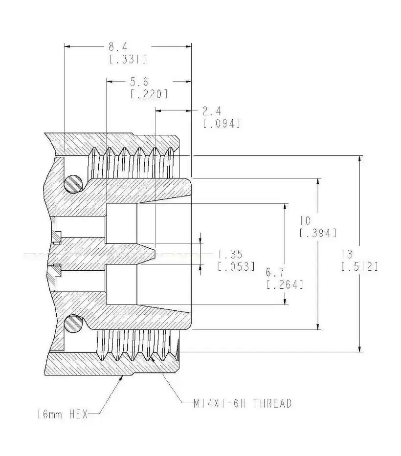
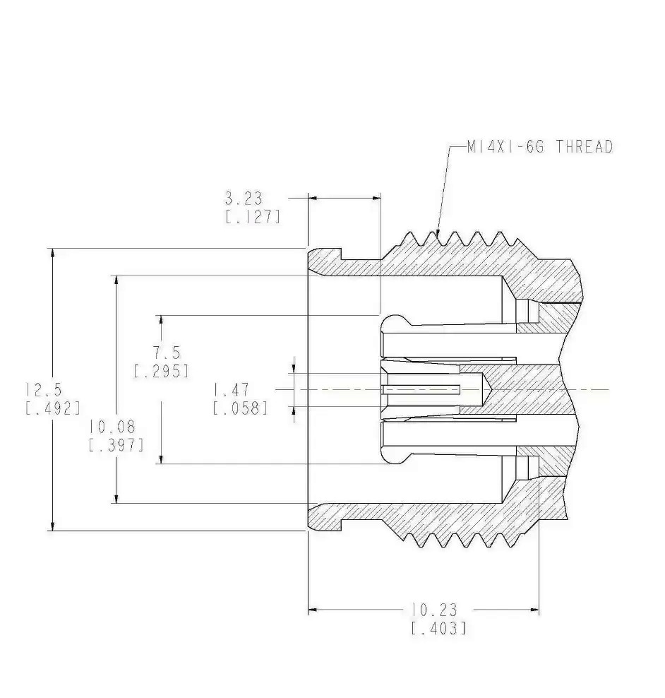
Interface Dimensions
Plug
Jack
Related Resources


Send us a Message
Please fill in the form below and we will contact you very soon.
Fields marked with an asterisk (*) are required.