4.1-9.5 Connectors
Compact high-power RF connectors offering waterproof reliability for telecom and broadcast systems
Overview
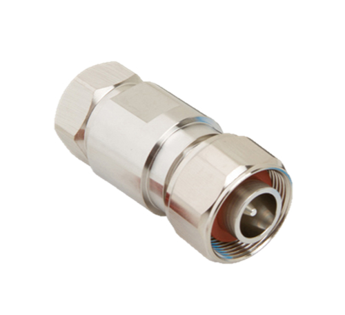
Amphenol RF’s 4.1‑9.5 connectors provide a high-power 50 Ω interface in a compact, rugged design. Ideal for telecom, broadcast and cellular infrastructure, these connectors support frequent mating and handle elevated RF power levels in space-constrained setups. With IP67-rated sealing and pull-push coupling, they deliver dependable performance in even harsh environments.
Sized between 4.3‑10 and 7‑16 standards, 4.1‑9.5 connectors offer up to 60% space savings. Their push-pull mating enables quick assembly without tools, while maintaining mechanical and electrical performance. Engineered for demanding deployments, these connectors make it easy to build durable, high-density RF networks.
Features and Benefits
- Compact form factor – Smaller than 4.3‑10 and 7‑16, ideal for tight installations
- High power capability – Supports robust RF power for telecom infrastructure
- IP67 sealed – Waterproof when mated for outdoor and indoor applications
- Quick push-pull coupling – Facilitates fast installation and maintenance
- Durable design – Precision-machined, marine-grade materials for long service life
Key Technical Details
- 50 Ω impedance optimized for high-power RF transmission
- Supports RF frequencies up to ~7.25 GHz (cable dependent)
- Push-pull coupling with positive lock ensures reliable mating
- IP67 rating when mated ensures environmental protection
- Compatible with RG-11, LMR-900 and similar ½″ diameter low-loss cables
Applications
- Cellular base stations & DAS – Rugged connectors for compact antenna systems
- Broadcast transmission lines – High-power, waterproof RF links in repeater sites
- Outdoor enclosures – IP67 sealing protects against moisture and dust
- RF system test environments – Push-pull coupling helps with rapid system setup
- Infrastructure upgrades – Easy-to-mate connectors fit dense rack-mounted equipment
Browse our full selection of 4.1‑9.5 connectors—including cable-mount plugs and panel jacks. If you need a tailor-made cable assembly, impedance adaptation, or unique mounting type, contact us today for an engineered solution.
Specifications
4.1-9.5 Connectors
Electrical
| Impedance | 50 Ohm |
| Frequency Range | DC - 14 GHz |
| Voltage Rating | 1400 Volts RMS Continuous |
| Dielectric Withstanding Voltage | 2500 VRMS Min |
| VSWR (Return Loss) | |
|
Straight DC - 0.5 GHz |
1.065 (-30 dB) Max |
|
Straight 0.5 - 4 GHz |
1.15 (-23 dB) Max |
|
Straight 4 - 10 GHz |
1.22 (-20 dB) Max |
| Insulation Resistance | 5000 MΩ Min |
| Center Contact Resistance | 1 mΩ Max |
| Outer Contact Resistance | 0.1 mΩ Max |
| RF Leakage | -128 dB Max (DC-1 GHz) |
| Insertion Loss | 0.05 √(f(GHz)) dB Max |
| Passive Intermodulation (PIM) | -160 dBc |
| Power Handling | 450 W @ 2 GHz @ 90 ºC |
Environmental
| Temperature Range | −40°C to +85°C |
| Thermal Shock
|
IEC 60068-2-14-NA
|
| Corrosion
|
MIL-STD-202, Method 101 (Test Condition B)
|
| Vibration
|
IEC 60068-2-6-FC
|
| Mechanical Shock
|
IEC 60068-2-27
|
| Moisture Resistance
|
IEC 60068 40/ 085/ 21
|
Mechanical
| Mating Cycles | 500 Min |
| Coupling Mechanism | Threaded
|
| Interface Specification | IEC 60169-11, DIN 47231
|
| Engagement Force
|
15 N (3.37 lb) Typ
|
| Disengagement Force
|
10 N (2.25 lb) Typ
|
| Mating Torque, Min Working
|
10 -12 N-m (88-106 in-lbs)
|
Note: These characteristics are typical and may not apply to all connectors.
Connector configurations may affect performance.
Related Resources

Send us a Message
Please fill in the form below and we will contact you very soon.
Fields marked with an asterisk (*) are required.