AFI Connectors
Blind‑mate board‑to‑board RF connectors with precision float for misaligned PCB designs
Overview
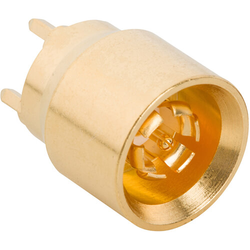
Amphenol RF’s AFI connector series provides a robust board‑to‑board RF interface that maintains signal integrity even when PCBs are misaligned. With a unique two-piece design incorporating an embedded bullet adapter, AFI connectors compensate for radial and axial misalignment, ensuring secure RF performance in precision assemblies. These connectors are available in both 50 Ω (DC–6 GHz) and 75 Ω (DC–3 GHz) variants to suit a range of high-frequency applications.
Engineered for demanding applications in military, broadband, telecom and routing equipment, the AFI series supports robust electrical performance and mechanical durability. Featuring blind-mate, push-on coupling and wear-resistant contacts, these connectors simplify assembly and maintenance in stacked-board configurations.
Features and Benefits
- Blind-mate, push-on interface enables crash-proof and easy PCB-to-PCB connections
- High misalignment tolerance – ±0.8 mm radial and ±1.0 mm axial float minimizes connection issues during assembly.
- Dual impedance support: 50 Ω version operates to 6 GHz, 75 Ω version to 3 GHz
- Flexible PCB mounting options support single and dual-row configurations
- Durable performance with ≥100 mating cycles, resistant to mechanical shock and vibration.
Key Technical Details
- 50 Ω version: DC–6 GHz; 75 Ω version: DC–3 GHz
- Misalignment compensation: 0.8 mm radial, 1.0 mm axial float
- Voltage rating: 335 V RMS continuous; dielectric withstand up to 1000 VRMS
- Insertion loss: 0.1√f (GHz) dB; return loss and VSWR per GHz bands (1.08–1.3)
- Power handling: 200 W @ 2.2 GHz @ 85 °C; operating temperature range −65 °C to +165 °C
Applications
- Military and aerospace – Suitable for rugged board stacking in high-reliability systems
- Broadband routers & switches – Supports floating board arrays and modular signal paths
- Wireless & telecom – Efficient PCB-to-PCB RF routing with alignment tolerance
- Cable modem termination systems (CMTS) – High-density board interconnects with minimal assembly risk
- Backplane and daughterboard mating – Simplifies integration in modular electronics architectures
Browse our complete AFI connector lineup—including 50 Ω and 75 Ω board plug and jack configurations. If you require custom PCB spacing, cable-to-board versions, or specialized coax interfaces, contact our engineering team to develop precision solutions tailored to your system.
Specifications
AFI Connectors
50 Ohm
Electrical
| Impedance | 50 Ohm |
| Frequency Range | DC - 6 GHz |
| Voltage Rating | 335 Volts RMS Max Continuous |
| Dielectric Withstanding Voltage | 1000 VRMS Max |
| VSWR (Return Loss) | |
DC - 1 GHz |
1.08 (-28 dB) Max |
1 - 3 GHz |
1.12 (-25 dB) Max |
3 - 6 GHz |
1.3 (-18 dB) Max |
| Insulation Resistance | 1000 MΩ Min |
| Center Contact Resistance | 5 mΩ Min |
| Outer Contact Resistance | 1 mΩ Min |
| RF Leakage | -70 dB Min (DC - 3 GHz) |
| Insertion Loss | .1 √(f(GHz)) dB Max |
| Power Handling | 200 W @ 2.2 GHz @ 85 ºC |
Environmental
| Temperature Range | −65°C to +165°C |
| Thermal Shock | EIA-364-32, Method A, Condition II, 25 Cycles |
| Corrosion | EIA-364-65, Condition IIA, 336 Hours |
| Vibration | EIA-364-28, Condition V, Letter C, for 120 minutes in each of 3 directions |
| Mechanical Shock | EIA-364-27, Condition A, 3 shocks in each direction (18 total) |
| Moisture Resistance | EIA-364-31, Method III, Condition B |
Mechanical
| Mating Cycles | 100 Min |
| Coupling Mechanism | Push-On |
| Interface Specification | Amphenol RF Proprietary |
| Engagement Force | 0.5 lbs |
| Disengagement Force | 0.5 - 3.0 lbs |
| Mechanical Misalignment | |
Axial |
1.00 mm |
Radial |
0.80 mm |
Min Board to Board Distance |
12.7 mm |
75 Ohm
Electrical
| Impedance | 75 Ohm |
| Frequency Range | DC- 3 GHz |
| Voltage Rating | 335 Volts RMS Max Continuous |
| Dielectric Withstanding Voltage | 1000 VRMS Max |
| VSWR (Return Loss) | |
DC - 2 GHz |
1.11 (-26 dB) Max |
2 - 3 GHz |
1.3 (-18 dB) Max |
| Insulation Resistance | 1000 MΩ Min |
| Center Contact Resistance | 7 mΩ Min |
| Outer Contact Resistance | 1 mΩ Min |
| RF Leakage | -70 dB Min (DC - 3 GHz) |
| Insertion Loss | .1 √(f(GHz)) dB Max |
| Power Handling | 95 W @ 1 GHz @ 25 ºC |
Environmental
| Temperature Range | −65°C to +165°C |
| Thermal Shock | EIA-364-32, Method A, Condition II, 25 Cycles |
| Corrosion | EIA-364-65, Condition IIA, 336 hours |
| Vibration | EIA-364-28, Condition V, Letter C, for 120 Minutes in each of 3 directions |
| Mechanical Shock | EIA-364-27, Condition A, 3 shocks in each direction (18 total) |
| Moisture Resistance | EIA-364-31, Method III, Condition B |
Mechanical
| Mating Cycles | 100 Min |
| Coupling Mechanism | Push-On |
| Interface Specification | Amphenol RF Proprietary |
| Engagement Force | 0.5 lbs |
| Disengagement Force | 0.5 - 3.0 lbs |
| Mechanical Misalignment | |
Axial |
1.00 mm |
Radial |
0.80 mm |
Min Board to Board Distance |
12.7 mm |
Note: These characteristics are typical and may not apply to all connectors.
Connector configurations may affect performance.
Related Resources


Send us a Message
Please fill in the form below and we will contact you very soon.
Fields marked with an asterisk (*) are required.