BNC Connectors
Trusted bayonet RF connectors for test, broadcast and general-purpose applications
Overview
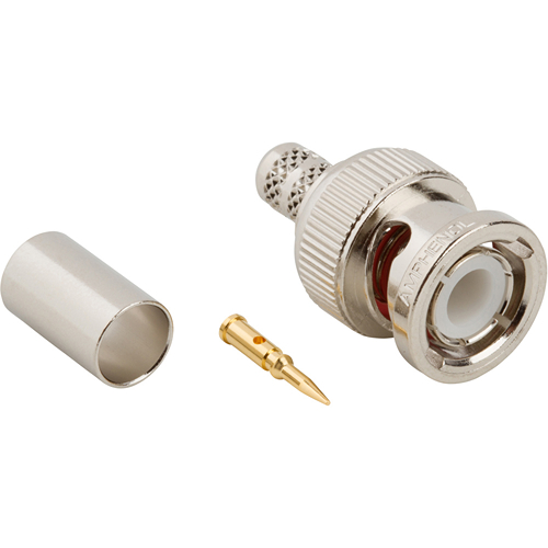
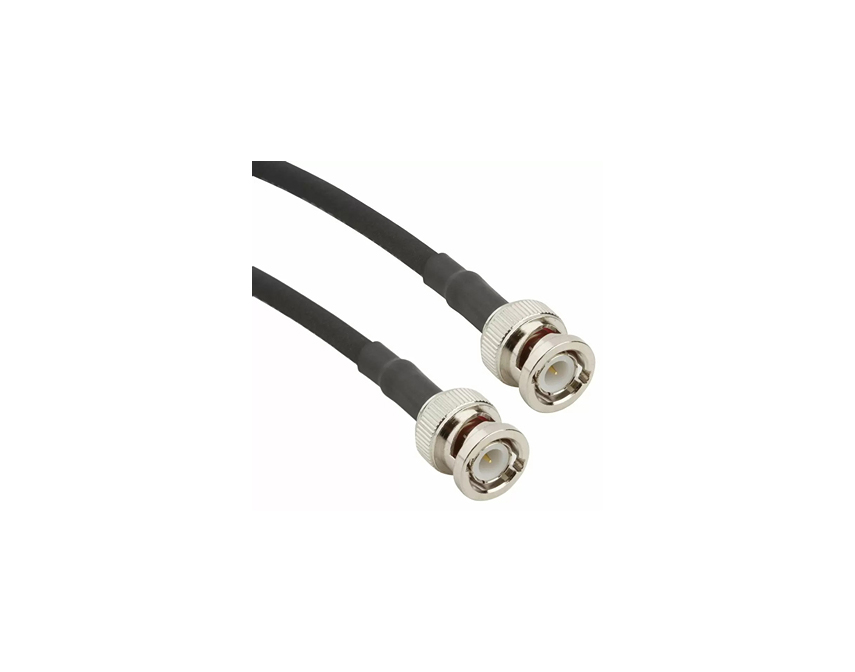
Amphenol RF’s BNC connector series provides a versatile and reliable bayonet-coupling interface that meets the needs of test labs, broadcast systems, and general-purpose RF and video setups. Designed for both 50 Ω and 75 Ω impedance environments, these connectors ensure quick, secure connections with consistent impedance matching and low-reflection performance—even under frequent usage.
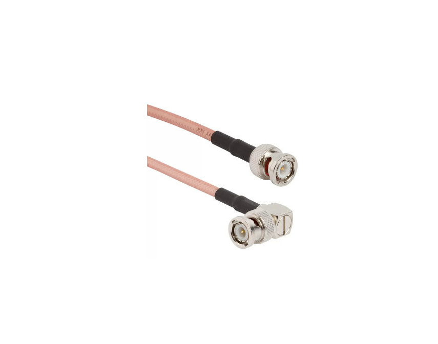
Engineered for durability and signal integrity, our BNC connectors support high-frequency video signals up to 12 GHz when paired with Amphenol RF’s 12G-capable broadcast cable assemblies. Whether used in instrumentation, live production, or everyday equipment, BNC connectors offer an economical yet professional-grade solution for clean signal transfer.
Features and Benefits
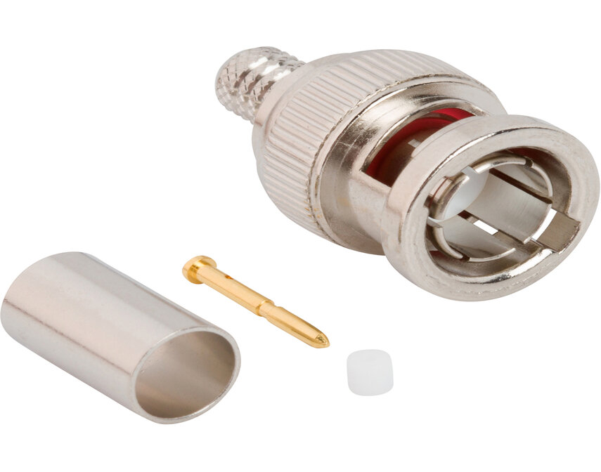
- Easy bayonet coupling enables fast, tool-less mating and secure retention
- Dual impedance support offers 50 Ω for general RF use and 75 Ω for high-bandwidth video systems
- High-frequency capability with broadcast-grade assemblies rated to 12 GHz
- Lab-grade durability—precision contacts withstand frequent mating cycles
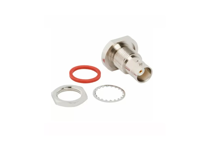
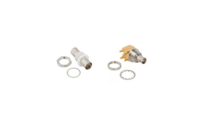
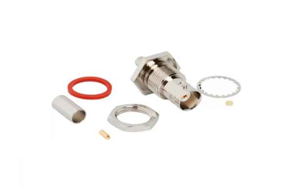
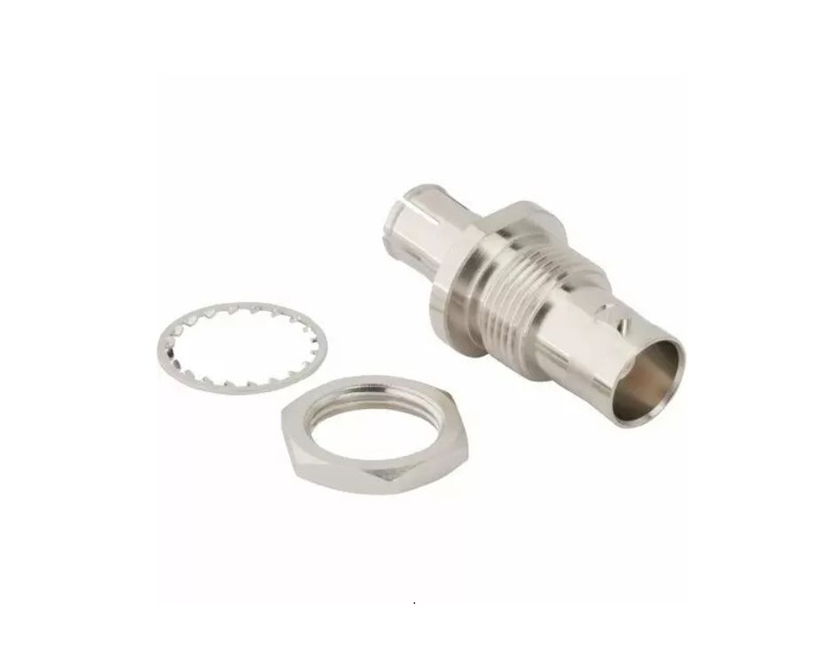
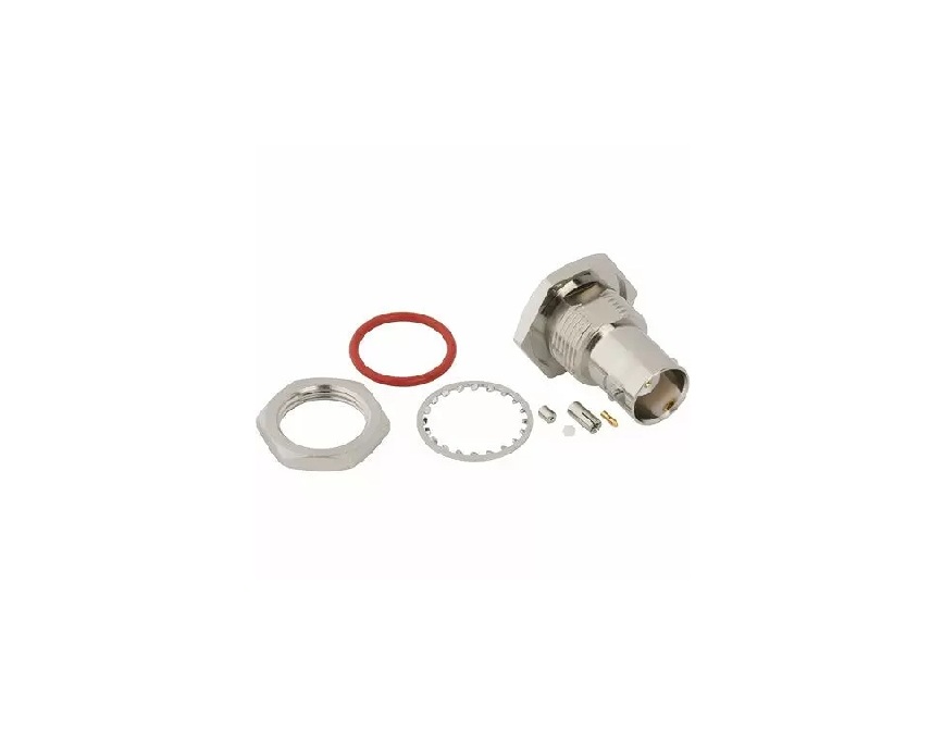
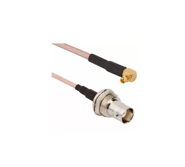
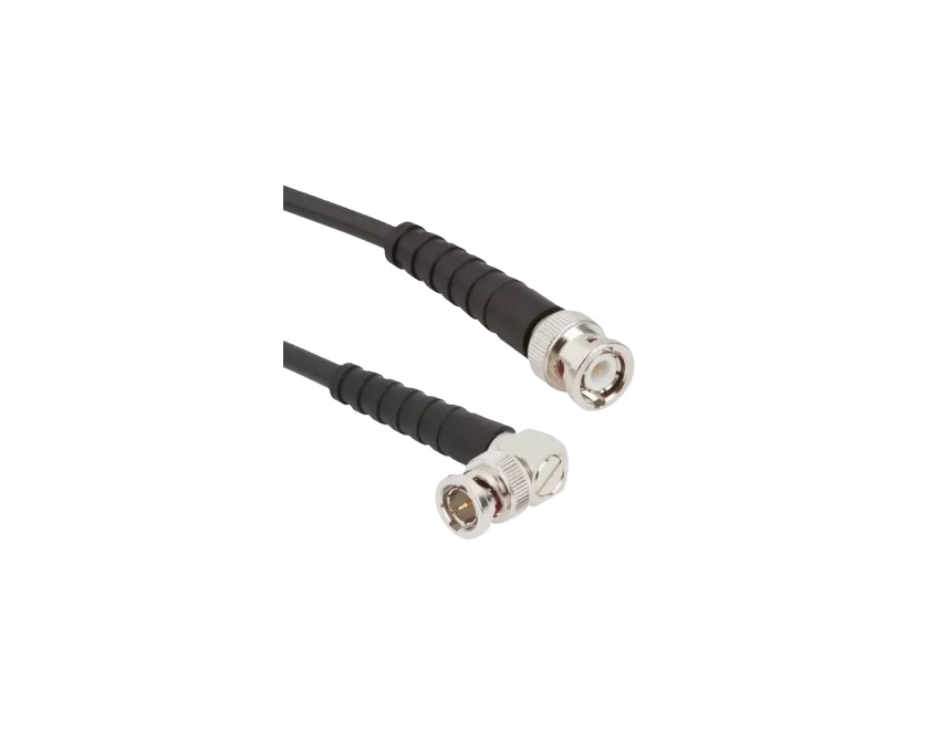
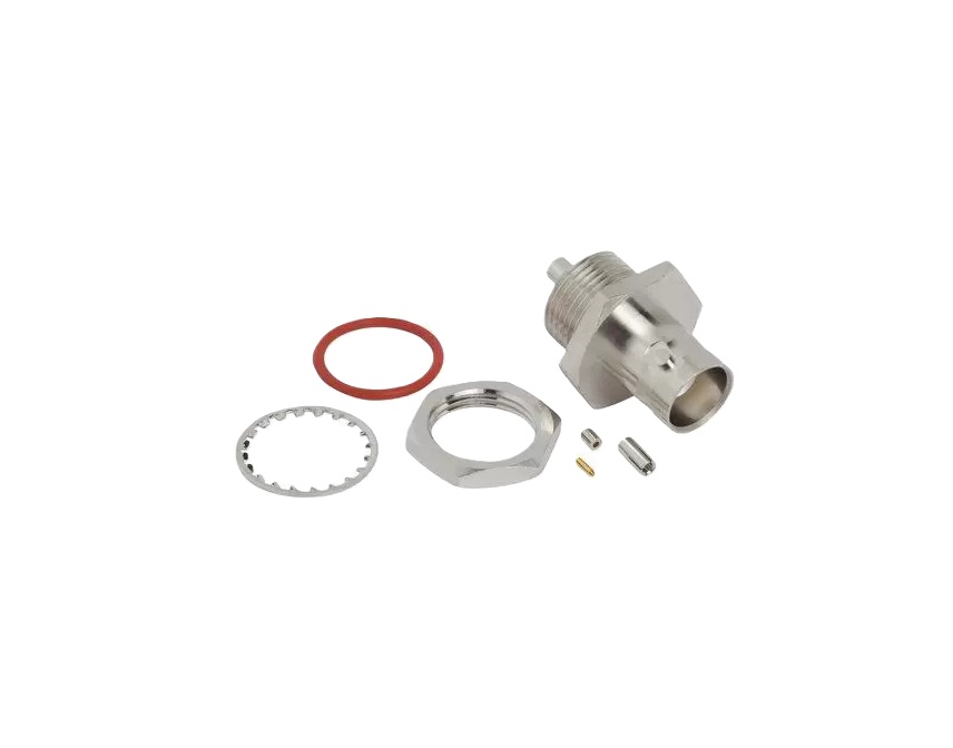
- Versatile form factors include cable-mount, panel-mount, right-angle, and bulkhead versions
Key Technical Details
- Impedance types: 50 Ω and 75 Ω variants available based on application
- Frequency rating: Standard RF to ~4 GHz; video-grade setups support up to 12 GHz (cable dependent)
- Coupling mechanism: Bayonet style for fast and reliable connections
- Contact integrity: Gold-plated contacts maintain consistent return and insertion loss
- Mounting options: Cable, panel, right-angle, and bulkhead versions to suit various installations
Applications
- Test instrumentation – oscilloscopes, signal generators, and analyzers
- Broadcast and production – high-bandwidth 12G SDI video systems
- Communications testbeds – RF labs and educational facilities
- Control and monitoring systems – secure signal pathways in industrial environments
- Legacy infrastructure – cost-effective, durable connectors for retrofit and maintenance
Browse our full BNC connector lineup to select the ideal impedance, mounting style, and frequency capability. For custom assemblies, specific cable pairings, or guidance on broadcast-grade requirements, contact our engineering team to explore tailored solutions.
Specifications
BNC Connectors
50 Ohm
Electrical
| Impedance | 50 Ohm |
| Frequency Range | DC - 4 GHz (DC -12 GHz on Extended Range Designs) |
| Voltage Rating | 500 Volts RMS Max Continuous |
| Dielectric Withstanding Voltage | 1500 VRMS Max |
| VSWR (Return Loss) | |
|
DC - 4 GHz
|
1.3 (-18 dB) Max |
| Insulation Resistance | 5000 MΩ Min |
| Center Contact Resistance | 1.5 mΩ Min |
| Outer Contact Resistance | 0.2 mΩ Min |
| RF Leakage | 55 dB Max @ 3 GHz |
| Insertion Loss | 0.2 dB Max @ 3 GHz |
| Power Handling | 316 W Max @ 1 GHz @ 25 ºC |
Environmental
| Temperature Range | −65°C to +165°C |
| Thermal Shock | MIL-STD-202, Method 107 (Test Condition G), except high temp test @ +200⁰C |
| Corrosion | MIL-STD-202, Method 101 (Test Condition B) - 5% Salt Solution |
| Vibration | MIL-STD-202, Method 204 (Test Condition D) |
| Mechanical Shock | MIL-STD-202, Method 213 (Test Condition G) - No Discontinuity Permitted |
| Moisture Resistance | MIL-STD-202, Method 106 |
| Altitude | MIL-STD-202 Method 105 (Test Condition C) |
Mechanical
| Mating Cycles | 500 Min |
| Coupling Mechanism | Bayonet |
| Interface Specification | MIL-STD-348 |
75 Ohm
Electrical
| Impedance | 75 Ohm |
| Frequency Range | DC- 4 GHz (DC - 12 GHz on Extended Range Designs) |
| Voltage Rating | 500 Volts RMS Max Continuous |
| Dielectric Withstanding Voltage | 1500 VRMS Max |
| VSWR (Return Loss) | |
|
DC - 4 GHz
|
1.5 (-14 dB) Max |
|
12G Products: DC - 6 GHz
|
1.22 (-20 dB) Max |
|
12G Products: 6 - 12 GHz
|
1.43 (-15 dB) Max |
| Insulation Resistance | 5000 MΩ Min |
| Center Contact Resistance | 1.5 mΩ Min |
| Outer Contact Resistance | 0.2 mΩ Min |
| RF Leakage | 55 dB Max @ 3 GHz |
| Insertion Loss | 0.2 dB Max @ 3 GHz |
| Power Handling | 316 W Max @ 1 GHz @ 25ºC |
Environmental
| Temperature Range | −65°C to +165°C
|
| Thermal Shock | MIL-STD-202, Method 107 (Test Condition G), except high temp test @ +200⁰C
|
| Corrosion | MIL-STD-202, Method 101 ( Test Condition B) - 5% Salt Solution
|
| Vibration
|
MIL-STD-202, Method 204 (Test Condition D) |
| Mechanical Shock
|
MIL-STD-202, Method 213 (Test Condition G) - No Discontinuity Permitted
|
| Moisture Resistance
|
MIL-STD-202, Method 106
|
| Altitude
|
MIL-STD-202, Method 105 (Test Condition C)
|
Mechanical
| Mating Cycles
|
500 Min
|
| Coupling Mechanism | Bayonet
|
| Interface Specification
|
MIL-STD-348
|
Note: These characteristics are typical and may not apply to all connectors.
Connector configurations may affect performance.
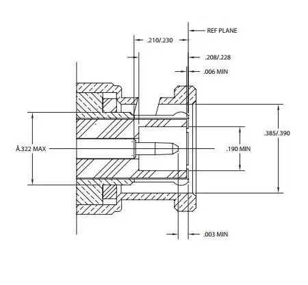
Interface Dimensions
Jack
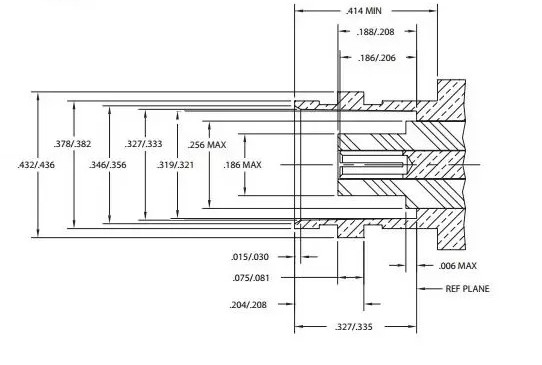
Plug
Related Resources


Send us a Message
Please fill in the form below and we will contact you very soon.
Fields marked with an asterisk (*) are required.