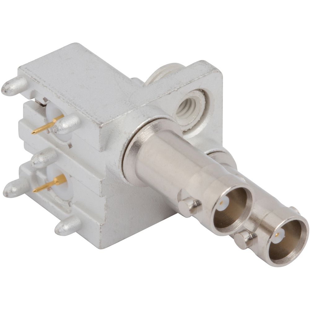
HD-BNC Connectors
High-density BNC connectors optimized for broadcast-quality RF performance
Overview
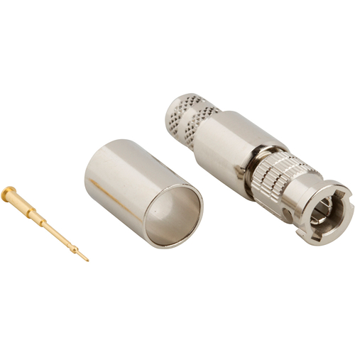
Amphenol RF’s HD‑BNC series delivers industry-leading 75 Ω performance in a compact, quarter-size footprint, enabling four times the density of traditional BNC connectors—ideal for modern broadcast, CATV, and high-speed video applications.
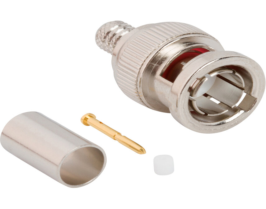
These connectors blend familiar bayonet coupling with precision design, offering up to 12 GHz signal integrity, ruggedized construction, and IP67 sealing options for demanding environments. Whether used in studio patch panels or industrial enclosures, HD‑BNC connectors ensure clean, reliable RF connections in high-density layouts.
Features and Benefits
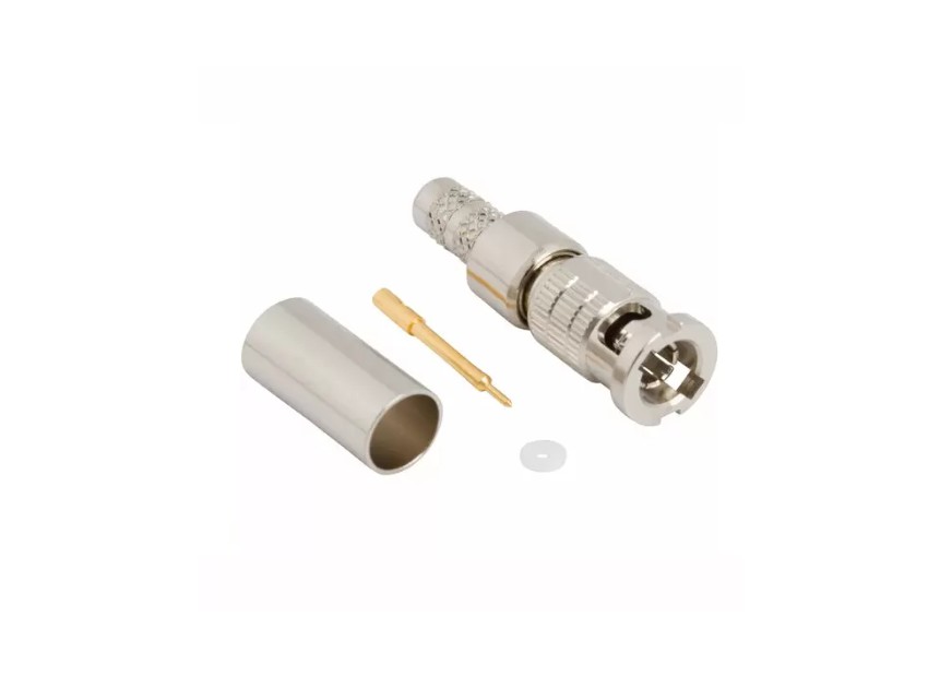
- Compact design—51% smaller than legacy BNC, enabling high-density configurations in modern systems
- True 75 Ω performance (also available in 50 Ω variants) with low insertion loss (<0.1 dB)
- Broadcast-grade frequency support up to 12 GHz for 12G‑SDI applications
- Rugged bayonet locking mechanism with tactile feedback, rated for ≥ 500 mating cycles
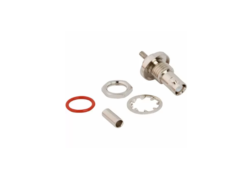
- Available IP67 versions with sealed, closed-entry design for harsh environments
Key Technical Details
- Impedance: 75 Ω standard (also offered in 50 Ω)
- Frequency Range: DC–6 GHz (standard); 6–12 GHz models for 12G‑SDI video
- Insertion Loss: ≤ 0.1 dB (f(GHz)^½)
- Voltage Rating: 170 VRMS; 500 VRMS dielectric withstanding
- Mechanical Coupling: Quarter-turn bayonet interface; ≥ 500 mating cycles
Applications
- 4K/Ultra-HD broadcast and production facilities
- Studio patch panels and high-density distribution systems
- Mobile broadcast cameras and field equipment
- Industrial and marine RF enclosures requiring robust, sealed connectivity
- Broadcast test gear and instrumentation supporting HD/12G‑SDI formats
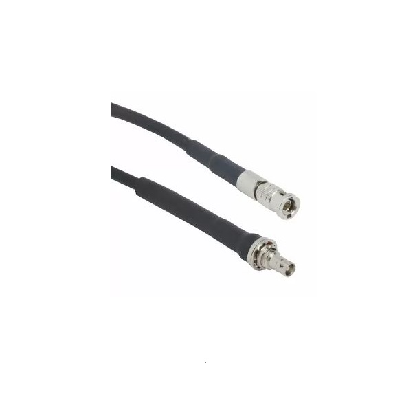
Browse our range of HD‑BNC connectors—including bulky‑proof IP67 jacks, board-mount types, terminations, and adapters. For custom cable assemblies, bulkhead connectors, or ruggedized solutions, contact our technical team to find the perfect fit.
Specifications
HD-BNC Connectors
50 Ohm
Electrical
| Impedance | 50 Ohm |
| Frequency Range | DC - 6 GHz
|
| Voltage Rating | 170 Volts RMS Max Continuous
|
| Dielectric Withstanding Voltage | 500 VRMS Max |
| VSWR (Return Loss) |
|
|
DC - 4 GHz
|
1.065 (-30 dB) Max
|
| Insulation Resistance | 10000 MΩ Min
|
| Center Contact Resistance | 5.0 mΩ Min
|
| Outer Contact Resistance | 2.5 mΩ Min
|
| RF Leakage | 60 dB Max @ 1 GHz
|
| Insertion Loss | .1 √(f(GHz)) dB Max
|
Environmental
| Temperature Range | −65°C to +165°C
|
| Thermal Shock | MIL-STD-202, Method 107 (Test Condition B), Except high temp test @ +200⁰C
|
| Corrosion | MIL-STD-202, Method 101 (Test Condition B) - 5% Salt Solution
|
| Vibration | MIL-STD-202, Method 204 (Test Condition B)
|
| Mechanical Shock | MIL-STD-202, Method 213 (Test Condition B)
|
| Moisture Resistance | MIL-STD-202, Method 106
|
Mechanical
| Mating Cycles
|
500 Min
|
| Coupling Mechanism | Bayonet
|
| Interface Specification
|
Amphenol RF Proprietary
|
75 Ohm
Electrical
| Impedance | 75 Ohm |
| Frequency Range | DC- 6 GHz (0 - 18 GHz on 12G Products)
|
| Voltage Rating | 170 Volts RMS Max Continuous
|
| Dielectric Withstanding Voltage | 500 VRMS Max
|
| VSWR (Return Loss) |
|
|
12G Products: DC - 6 GHz
|
1.22 (-20 dB) Max |
|
12G Products: 6 - 12 GHz
|
1.43 (-15 dB) Max |
| Insulation Resistance | 10000 MΩ Min
|
| Center Contact Resistance | 5.0 mΩ Min
|
| Outer Contact Resistance | 2.5 mΩ Min
|
| RF Leakage | 60 dB Max @ 3 GHz
|
| Insertion Loss | .1 √(f(GHz)) dB Max
|
Environmental
| Temperature Range | −65°C to +165°C
|
| Thermal Shock | MIL-STD-202, Method 107 (Test Condition B), except high temp test @ +200⁰C
|
| Corrosion | MIL-STD-202, Method 101 ( Test Condition B) - 5% Salt Solution
|
| Vibration
|
MIL-STD-202, Method 204 (Test Condition B)
|
| Mechanical Shock
|
MIL-STD-202, Method 213 (Test Condition B)
|
| Moisture Resistance
|
MIL-STD-202, Method 106
|
Mechanical
| Mating Cycles
|
500 Min
|
| Coupling Mechanism | Bayonet
|
| Interface Specification
|
Amphenol RF Proprietary
|
Note: These characteristics are typical and may not apply to all connectors.
Connector configurations may affect performance.
Related Resources


Send us a Message
Please fill in the form below and we will contact you very soon.
Fields marked with an asterisk (*) are required.