PSMP Connectors
High-power, board-to-board RF interconnects for next-gen systems
Overview
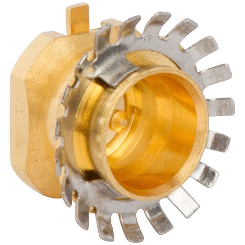
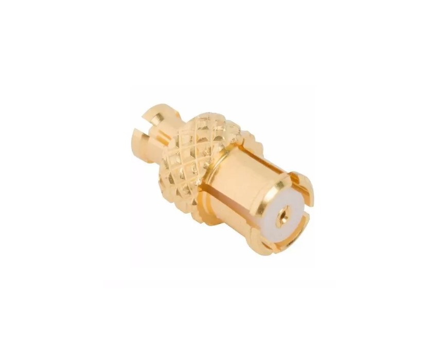
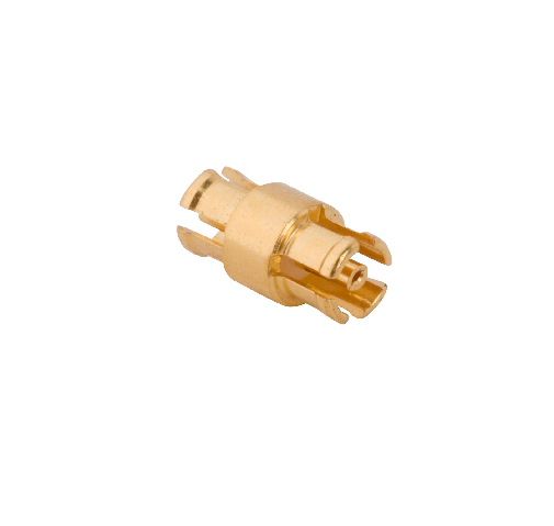
Amphenol RF’s PSMP connectors are engineered for board-to-board applications demanding both high power and RF performance. The compact, three-piece blind-mate design ensures reliable mating in tight spaces, while offering the same PCB footprint as SMP for design flexibility.
Supporting continuous power up to 200 W at 2.2 GHz and operation up to 10 GHz, PSMP connectors feature generous axial and radial misalignment tolerances—ideal for base stations, amplifiers, filters, handheld radios and other rugged RF applications.
Features and Benefits
- High power capacity: 200 W continuous at 2.2 GHz
- Wideband RF performance: Frequency range up to 10 GHz
- Robust blind-mate design: ±1 mm axial misalignment, snap-on coupling
- Compact and backward compatible: Maintains SMP PCB footprint
- Multiple coupling styles: Smooth bore, limited detent, full detent options
Key Technical Details
- Impedance: 50 Ω
- Operating frequency: Up to 10 GHz (cable/PCB dependent)
- Power handling: 200 W continuous at 2.2 GHz
- Misalignment tolerances: ±1 mm axial; radial flexibility per design variant
- Voltage rating: 480 Vrms; dielectric withstanding 1000 Vrms
Applications
- Telecom base stations & radio front-ends
- RF amplifier modules & filters
- Handheld and portable radio equipment
- Industrial and test instrumentation
- High-density, power-distributed PCB environments
Explore our standard PSMP lineup for robust high-frequency, high-power board-to-board interconnects. If your application requires modified coupling styles, spacing, or custom configurations, our engineering team is ready to assist with tailored PSMP solutions.
Specifications
PSMP Connectors
Electrical
| Impedance | 50 Ohm |
| Frequency Range | DC - 10 GHz |
| Voltage Rating | 480 Volts RMS Continuous |
| Dielectric Withstanding Voltage | 1000 VRMS Max |
| VSWR (Return Loss) | |
|
DC - 3 GHz
|
1.052 (-32 dB) Max |
|
3 - 6 GHz
|
1.11 (-26 dB) Max |
| Insulation Resistance | 5000 MΩ Min |
| Center Contact Resistance | 3 mΩ Max |
| Outer Contact Resistance | 2 mΩ Max |
| RF Leakage | -75 dB Max (DC - 4 GHz) |
| Insertion Loss | .03 √(f(GHz)) dB Max |
| Passive Intermodulation (PIM) | -160 dBc with 2 X 43 dBm inputs |
| Power Handling | 200 W @ 2.2 GHz @ 85ºC |
Environmental
| Temperature Range | −65°C to +165°C |
| Thermal Shock | IEC 60169-1, Subclause 16.4 (-65 °C to +165 °C) |
| Vibration | IEC 60068-2-64 Random |
| Mechanical Shock | IEC 60068-2-27 (50g, 11 ms, half-sine) |
Mechanical
| Mating Cycles | 100 Min (Detent), 1000 Min (Smooth Bore) |
| Coupling Mechanism | Push-On |
| Interface Specification | Rosenberger PSMP |
| Engagement Force | |
|
Limited Detent
|
≤ 45 N |
|
Smooth Bore, Catchers Mitt
|
≤ 10 N |
| Disengagement Force | |
|
Limited Detent
|
≤ 15 N |
|
Smooth Bore, Catchers Mitt
|
≤ 2.2 N |
| Mechanical Misalignment | |
|
Axial
|
± 1 mm |
|
Radial
|
4° |
|
Min Board to Board Distance
|
12.6 mm |
Note: These characteristics are typical and may not apply to all connectors.
Connector configurations may affect performance.
Related Resources


Send us a Message
Please fill in the form below and we will contact you very soon.
Fields marked with an asterisk (*) are required.