QN Connectors
Reliable, quick-connect RF solutions for panels, test fixtures and cable assemblies
Overview
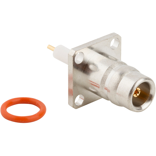
Amphenol RF’s QN connectors deliver robust performance in applications where speed and bandwidth are essential. Featuring a quarter-turn quick-connect interface, QN offers fast mating and demating without compromising signal integrity or durability.
Engineered for both flexibility and reliability, QN connectors support applications from lab test setups to telecom and defense systems. They are available in adapter, bulkhead, cable-mount and panel-mount formats—providing versatility to suit various engineering needs.
Features and Benefits
- Quick, secure mating: ¼‑turn coupling mechanism ensures fast connect/disconnect while maintaining RF performance
- High-frequency capability: Optimized for broadband applications up to 4 GHz
- Durable construction: Stainless steel shells and gold-plated centers withstand rugged environments
- Versatile mounting: Cable, panel, bulkhead and adapter configurations offer design flexibility
- Test-friendly: Ideal for lab and fixture use, enabling reliable throughput with repeated mating
Key Technical Details
- Impedance: 50 Ω
- Frequency range: DC – 4 GHz (connector + cable dependent)
- Mating cycles: 500 minimum typical, varies by assembly
- Temperature rating: –55 °C to +165 °C (connector materials based)
- Corrosion resistance: Stainless steel shell with passivation
Applications
- RF test fixtures and instrumentation
- Telecom equipment patching and calibration
- Defense and aerospace RF cabling
- Panel-mounted RF interfaces
- Prototyping and lab environments
Explore Amphenol RF’s catalog of QN connectors for standard quick-connect panels and cable assemblies. For custom variations—such as specific lengths, terminations, or material finishes—our engineering team is ready to assist. Contact us to discuss your custom requirements.
Specifications
QN Connectors
Electrical
| Impedance | 50 Ohm |
| Frequency Range | DC - 11 GHz |
| Voltage Rating | 500 Volts RMS Continuous |
| Dielectric Withstanding Voltage | 2500 VRMS Max |
| VSWR (Return Loss) | |
|
DC - 3 GHz
|
1.052 (-32 dB) Max |
|
3 - 6 GHz
|
1.12 (-25 dB) Max |
|
6 - 11 GHz
|
1.22 (-20 dB) Max |
| Insulation Resistance | 5000 MΩ Min |
| Center Contact Resistance | 1.5 mΩ Max |
| Outer Contact Resistance | 1.5 mΩ Max |
| RF Leakage | -90 dB Max (DC - 3 GHz) |
| Insertion Loss | .03 √(f(GHz)) dB Max |
| Power Handling | 300 W @ 2.5 GHz @ 25ºC |
Environmental
| Temperature Range | −40°C to +125°C |
| Thermal Shock | IEC 60169-1 16.4 (-40⁰C to +125⁰C) |
| Corrosion | MIL-STD-202, Method 101 (Test Condition B) |
| Vibration | IEC-1169-1 Paragraph 9.3.3 (10-500 Hz;5g) |
| Moisture Resistance | MIL-STD-202 F, Method 106 F |
Mechanical
| Mating Cycles | 100 Min |
| Coupling Mechanism | Push-Pull |
| Interface Specification | Quick Lock Formula - QN |
| Engagement Force | 6.75 lbs (30 N) Typ |
| Disengagement Force | 6.75 lbs (30 N) Type |
Note: These characteristics are typical and may not apply to all connectors.
Connector configurations may affect performance.
Send us a Message
Please fill in the form below and we will contact you very soon.
Fields marked with an asterisk (*) are required.