RF Switching Connectors
Built-in test access and signal routing in compact, board-level RF solutions
Overview
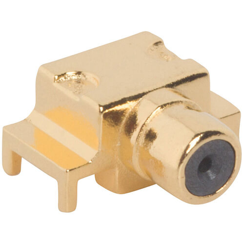
Amphenol RF’s RF switching connectors provide a robust, cost-effective method for testing RF circuits without the need to physically disconnect and reconnect cables. These connectors integrate a mechanical switch function that allows signal continuity during normal operation and redirects signals during test procedures.
Designed for durability and ease of use, RF switching connectors are available in several industry-standard interfaces such as SMA and MCX. They are ideal for PCB-mounted designs in compact environments where maintaining signal integrity and maximizing board space is essential.
Features and Benefits
- Integrated switch function eliminates the need for external switching hardware
- Compact PCB-mountable designs optimize limited board space
- Available in popular interfaces like SMA and MCX for seamless design integration
- Durable construction supports multiple test cycles
- Enables non-intrusive testing, improving reliability and reducing wear on cables
Key Technical Details
- Available in 50 ohm configurations
- Frequency support up to 6 GHz (cable and PCB dependent)
- Designed for standard board-to-instrumentation signal access
- Switch functionality rated for repeated test cycles
- PCB-mount designs with secure through-hole or surface mount footprints
Applications
- RF device production testing
- Wireless module validation
- Portable RF instruments
- IoT and consumer electronics diagnostics
- Antenna switch modules
Browse our standard RF switching connector options for streamlined test integration. If your application requires custom PCB layouts, frequency support, or switching functionality, contact us for tailored design support.
Specifications
4.3/10 Connectors
Electrical
| Impedance | 50 Ω |
| Frequency Range | DC to 6 GHz |
| Voltage Rating | X Volts RMS Continuous |
| Dielectric Withstanding Voltage | X VRMS Max |
| VSWR | XX (X.XX dB) |
| DC - X GHz | XX (X.XX dB) |
| X - Y GHz | XX (X.XX dB) |
| Y - Z GHz | XX (X.XX dB) |
| Insulation Resistance | XXXX MΩ min |
| Contact Resistance | |
| Center Contact | X.X mΩ Min |
| Outer Contact | X.X mΩ Min |
| RF Leakage | -XX dB Min |
| Insertion Loss | XX dB Max |
| Passive Intermodulation (PIM) | XX dBc with 2 X 43 dBm inputs |
| Power Handling | XX W @ XX GHz @ XX ºC |
Environmental
| Temperature Range | −55 to +90 °C |
| Thermal Shock | MIL-STD-202… |
| Corrosion | MIL-STD-202… |
| Vibration | MIL-STD-202… |
| Mechanical Shock | MIL-STD-202… |
| Moisture Resistance | MIL-STD-202… |
| Altitude | MIL-STD-202… |
Mechanical
| Mating Cycles | XXX Min |
| Coupling Mechanism | |
| Interface Specification | MIL-STD-348 |
| Engagement Force
|
XX lbs (XX N) |
| Disengagement Force | XX lbs (XX N) |
| Mating Torque, Min Working
|
inch-pounds |
| Mechanical Misalignment | |
| Axial | |
| Radial | |
| Max Float Angle | |
| Min Board to Board Distance | XX mm |
Note: These characteristics are typical and may not apply to all connectors.
Connector configurations may affect performance.
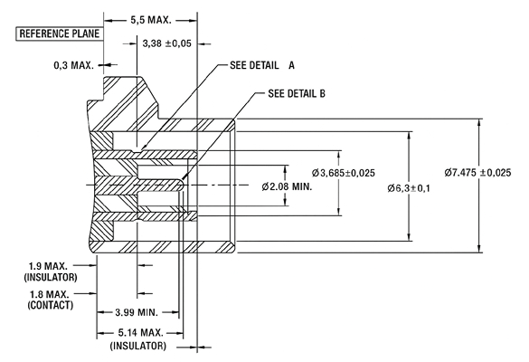
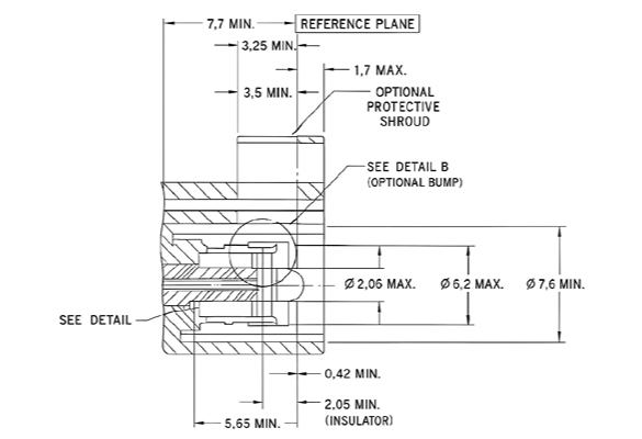
Interface Dimensions
Plug
Jack
Send us a Message
Please fill in the form below and we will contact you very soon.
Fields marked with an asterisk (*) are required.