RP-BNC Connectors
Reliable reversed-polarity BNC connectors built for critical RF applications
Overview
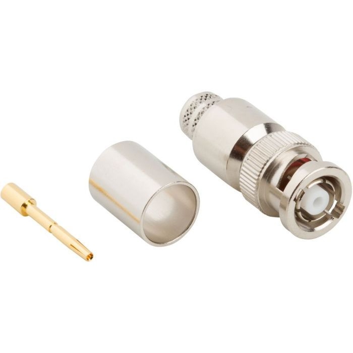
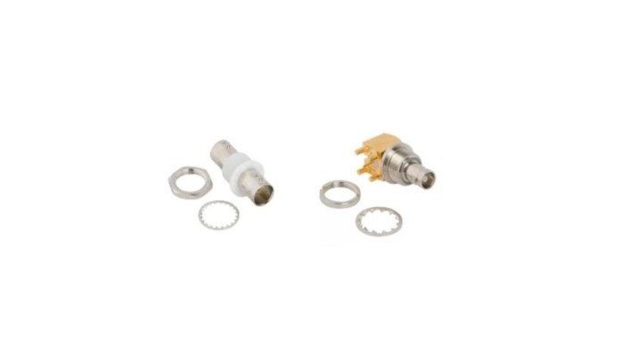
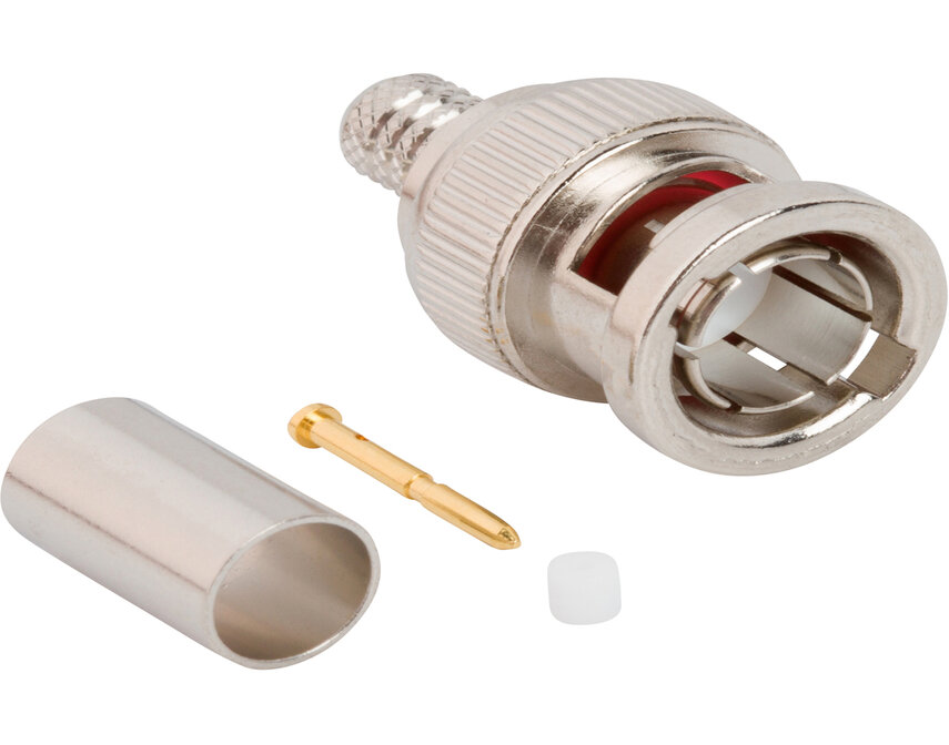
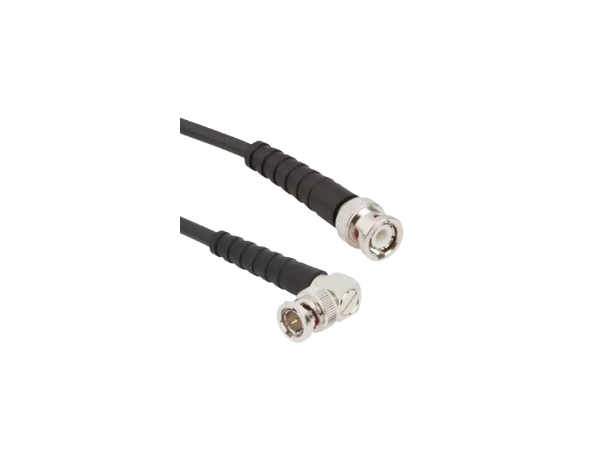
Amphenol RF’s RP‑BNC connectors provide the same secure bayonet-style connection as standard BNC but with a reversed center pin polarity. This design safeguards against unintended connections and ensures compliance with RF safety standards. Built for dependable performance across test equipment, communication gear and broadcast systems.
Engineered for frequent use in laboratory, field and embedded electronics environments, RP‑BNC connectors offer robust, user-friendly assembly in 50 Ω systems. Tested for high durability and signal integrity, they are ideal for applications demanding secure, reversible connections with continuity testing assurance.
Features and Benefits
- Reversed-polarity design enhances safety and regulatory compliance
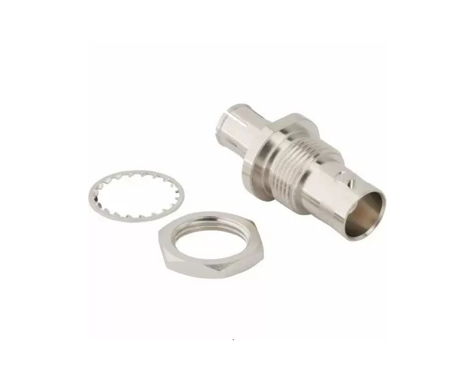
- Secure 2‑lug bayonet coupling with positive engagement
- 50 Ω impedance for broad RF compatibility and performance
- Tested for continuity and hi-pot on all standard assemblies
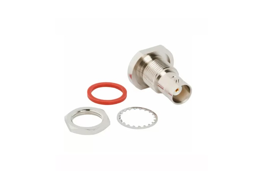
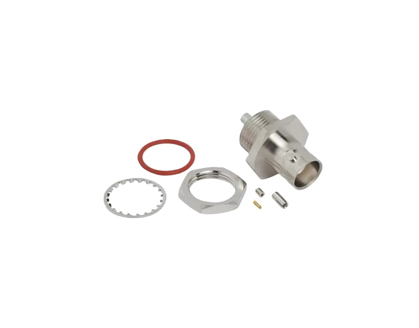
- Nickel or gold-plated options for corrosion resistance
Key Technical Details
- Impedance: 50 Ω matched
- Frequency range: Typically DC–4 GHz (connector + cable dependent)
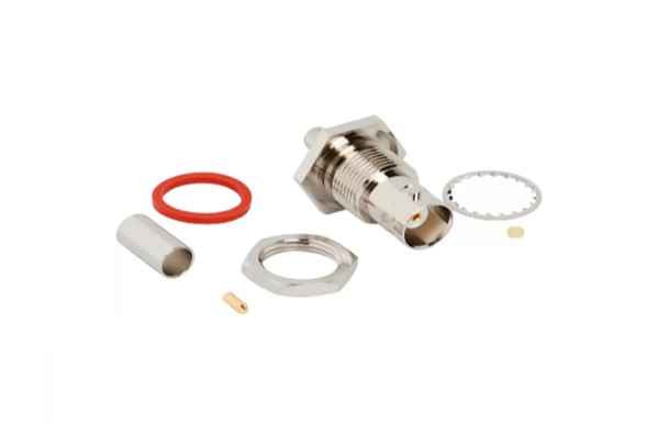
- Materials: Brass shell with optional plating for environmental resilience
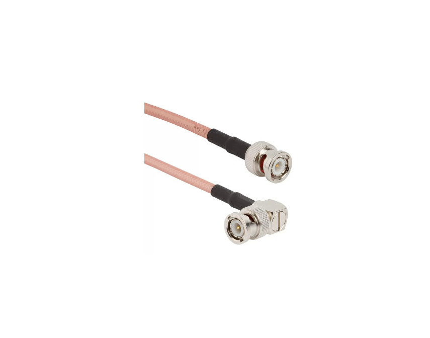
- Coupling type: BNC-style bayonet with twist lock
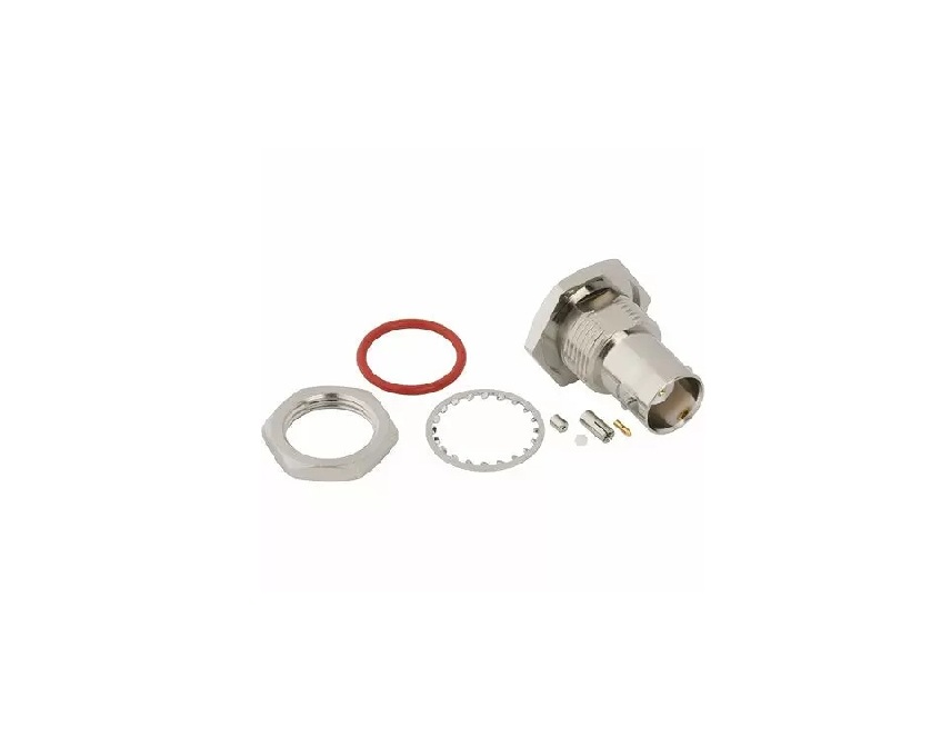
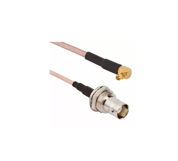
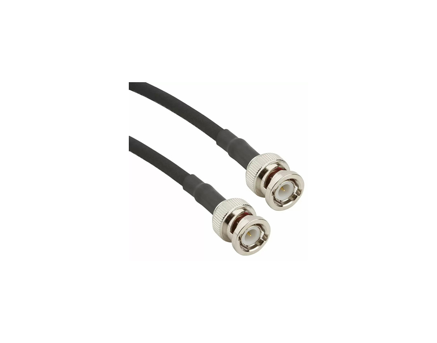
- Configuration: Available cable-to-cable, cable-to-panel and test cable versions
Applications
- RF test and measurement instrumentation
- Wireless communication and repeater setups
- Broadcast and video systems
- Antenna tuning and lab applications
- Embedded systems requiring reversible safe connectors
Explore our selection of standard RP‑BNC connectors. For customized cable lengths, environmental protection, or ruggedized variants, please contact our team.
Specifications
BNC Connectors
50 Ohm
Electrical
| Impedance | 50 Ohm |
| Frequency Range | DC - 4 GHz (DC -12 GHz on Extended Range Designs) |
| Voltage Rating | 500 Volts RMS Max Continuous |
| Dielectric Withstanding Voltage | 1500 VRMS Max |
| VSWR (Return Loss) |
|
|
DC - 4 GHz
|
1.3 (-18 dB) Max |
| Insulation Resistance | 5000 MΩ Min |
| Center Contact Resistance | 1.5 mΩ Min |
| Outer Contact Resistance | 0.2 mΩ Min |
| RF Leakage | 55 dB Max @ 3 GHz |
| Insertion Loss | 0.2 dB Max @ 3 GHz |
| Power Handling | 316 W Max @ 1 GHz @ 25 ºC |
Environmental
| Temperature Range | −65°C to +165°C |
| Thermal Shock | MIL-STD-202, Method 107 (Test Condition G), except high temp test @ +200⁰C |
| Corrosion | MIL-STD-202, Method 101 (Test Condition B) - 5% Salt Solution |
| Vibration | MIL-STD-202, Method 204 (Test Condition D) |
| Mechanical Shock | MIL-STD-202, Method 213 (Test Condition G) - No Discontinuity Permitted |
| Moisture Resistance | MIL-STD-202, Method 106 |
| Altitude | MIL-STD-202 Method 105 (Test Condition C) |
Mechanical
| Mating Cycles | 500 Min |
| Coupling Mechanism | Bayonet |
| Interface Specification | MIL-STD-348 |
75 Ohm
Electrical
| Impedance | 75 Ohm |
| Frequency Range | DC- 4 GHz (DC - 12 GHz on Extended Range Designs) |
| Voltage Rating | 500 Volts RMS Max Continuous |
| Dielectric Withstanding Voltage | 1500 VRMS Max |
| VSWR (Return Loss) | |
|
DC - 4 GHz
|
1.5 (-14 dB) Max |
|
12G Products: DC - 6 GHz
|
1.22 (-20 dB) Max |
|
12G Products: 6 - 12 GHz
|
1.43 (-15 dB) Max |
| Insulation Resistance | 5000 MΩ Min |
| Center Contact Resistance | 1.5 mΩ Min |
| Outer Contact Resistance | 0.2 mΩ Min |
| RF Leakage | 55 dB Max @ 3 GHz |
| Insertion Loss | 0.2 dB Max @ 3 GHz |
| Power Handling | 316 W Max @ 1 GHz @ 25ºC |
Environmental
| Temperature Range | −65°C to +165°C |
| Thermal Shock | MIL-STD-202, Method 107 (Test Condition G), except high temp test @ +200⁰C |
| Corrosion | MIL-STD-202, Method 101 ( Test Condition B) - 5% Salt Solution |
| Vibration | MIL-STD-202, Method 204 (Test Condition D) |
| Mechanical Shock | MIL-STD-202, Method 213 (Test Condition G) - No Discontinuity Permitted |
| Moisture Resistance | MIL-STD-202, Method 106 |
| Altitude | MIL-STD-202, Method 105 (Test Condition C) |
Mechanical
| Mating Cycles | 500 Min |
| Coupling Mechanism | Bayonet |
| Interface Specification | MIL-STD-348 |
Note: These characteristics are typical and may not apply to all connectors.
Connector configurations may affect performance.
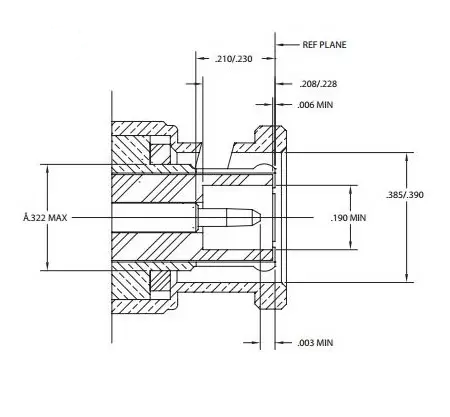
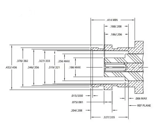
Interface Dimensions
Plug
Jack
Related Resources


Send us a Message
Please fill in the form below and we will contact you very soon.
Fields marked with an asterisk (*) are required.