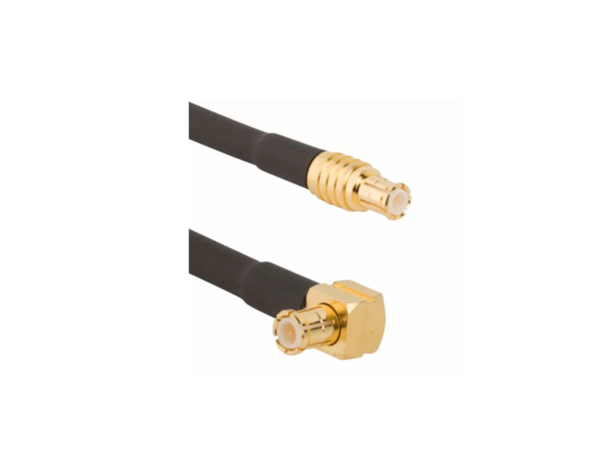
RP-MCX Connectors
Secure reverse-polarity MCX connectors for compact, high-frequency applications
Overview
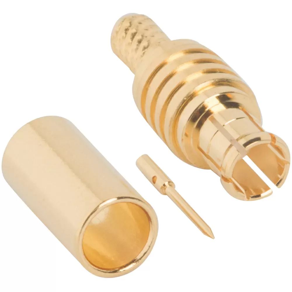
Amphenol RF’s RP‑MCX connectors combine the compact size of MCX with added safety and regulatory compliance through reverse-polarity construction. Engineered to reduce accidental mating with standard MCX, they offer reliable performance in tight spaces with secure locking. Ideal for professionals managing regulated wireless systems where connector polarity matters.
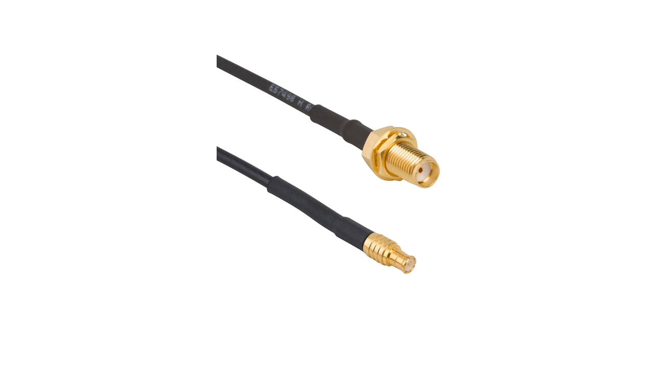
Offering broad frequency coverage up to 6 GHz (depending on cable), RP‑MCX connectors ensure signal integrity in RF monitoring, test equipment and wireless infrastructure. Their small form factor and reliable snap‑on coupling make them a preferred choice for portable and embedded RF devices.
Features and Benefits
- Reverse polarity design prevents accidental mating with MCX, supporting regulatory compliance
- Compact snap‑on coupling for fast, reliable connections in confined spaces
- Frequency support up to 6 GHz (cable dependent), with low insertion loss
- Gold-plated contacts ensure superior signal clarity and corrosion resistance
- Compatible with a wide range of miniature cable assemblies for versatile deployment
Key Technical Details
- Impedance: 50 Ω
- Service up to 6 GHz, depending on cable and assembly
- Durable coupling mechanism with secure retention
- Constructed from gold-plated brass for excellent conductivity
- Compact design optimized for space-constrained RF modules
Applications
- Portable RF and spectrum monitoring equipment
- Wireless device testing and diagnostics
- GPS, IoT and telemetry systems
- Embedded and wearable RF electronics
- Cellular network infrastructure and maintenance gear
Explore our RP‑MCX standard products to find reliable, compact RF interconnects. If your project demands custom plating, cable type, or performance tuning, our engineering team can assist with tailored RP‑MCX solutions.
Specifications
MCX Connectors
50 Ohm
Electrical
| Impedance | 50 Ohm |
| Frequency Range | DC - 6 GHz |
| Voltage Rating | 2255 Volts RMS Max Continuous |
| Dielectric Withstanding Voltage | 1000 VRMS Max |
| VSWR (Return Loss) | |
|
DC - 6 GHz
|
1.3 (-18 dB) Max |
| Insulation Resistance | 10000 MΩ Min |
| Center Contact Resistance | 5 mΩ Min |
| Outer Contact Resistance | 1 mΩ Min |
| RF Leakage | -60 dB Max @ 1 GHz |
| Insertion Loss | 0.10 db Max @ 1 GHz |
| Power Handling | 95 W Max @ 1 GHz @ 25 ºC |
Environmental
| Temperature Range | −65°C to +165°C |
| Thermal Shock | MIL-STD-202, Method 107 (Test Condition B), Except high temperatures @ +200⁰C |
| Corrosion | MIL-STD-202, Method 101 (Test Condition B) - 5% Salt Solution |
| Vibration | MIL-STD-202, Method 204, Snap-On (Test Condition B) |
| Mechanical Shock | MIL-STD-202, Method 213, Snap-On (Test Condition B) |
| Moisture Resistance | MIL-STD-202, Method 106 |
Mechanical
| Mating Cycles | 500 Min |
| Coupling Mechanism | Push-On |
| Interface Specification | CECC 22220 |
| Engagement Force | 20 N Max |
| Disengagement Force | 10 N Min |
75 Ohm
Electrical
| Impedance | 75 Ohm |
| Frequency Range | DC - 6 GHz (0 - 18 GHz on 12G Products) |
| Voltage Rating | 170 Volts RMS Max Continuous |
| Dielectric Withstanding Voltage | 500 VRMS Max |
| VSWR (Return Loss) | |
|
12G Products: DC - 6 GHz
|
1.22 (-20 dB) Max |
|
12G Products: 6 - 12 GHz
|
1.43 (-15 dB) Max |
| Insulation Resistance | 10000 MΩ Min |
| Center Contact Resistance | 5 mΩ Min |
| Outer Contact Resistance | 2.5 mΩ Min |
| RF Leakage | -60 dB Max @ 1 GHz |
| Insertion Loss | 0.10 dB Max @ 1 GHz |
| Power Handling | 95 W Max @ 1 GHz @ 25 ºC |
Environmental
| Temperature Range | −65°C to +165°C |
| Thermal Shock | MIL-STD-202, Method 107 (Test Condition B), Except high temperatures @ +200⁰C |
| Corrosion | MIL-STD-202, Method 101 (Test Condition B) - 5% Salt Solution |
| Vibration | MIL-STD-202, Method 204, Snap-On (Test Condition B) |
| Mechanical Shock | MIL-STD-202, Method 213, Snap-On (Test Condition B) |
| Moisture Resistance | MIL-STD-202, Method 106 |
Mechanical
| Mating Cycles | 500 Min |
| Coupling Mechanism | Push-On |
| Interface Specification | CECC 22220 |
| Engagement Force | 10 N Max |
| Disengagement Force | 10 N Min |
Note: These characteristics are typical and may not apply to all connectors.
Connector configurations may affect performance.
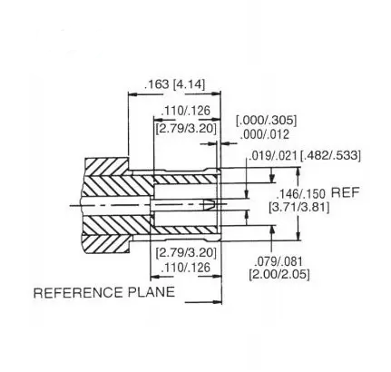
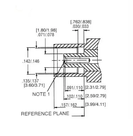
Interface Dimensions
Plug
Jack
Related Resources
.png)


")

Send us a Message
Please fill in the form below and we will contact you very soon.
Fields marked with an asterisk (*) are required.