RP-MMCX Connectors
Reverse‑polarity MMCX connectors engineered for secure, compact RF interconnects
Overview
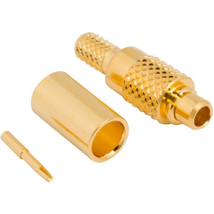
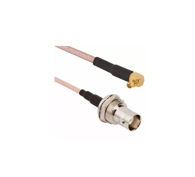
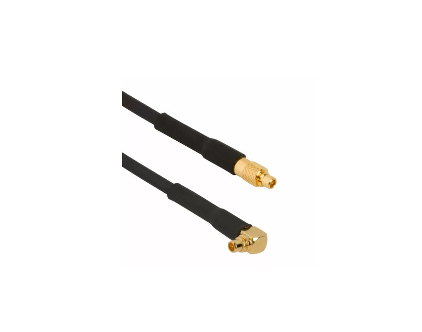
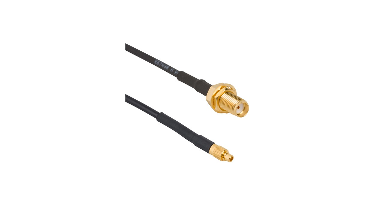
Amphenol RF’s RP‑MMCX connectors merge miniature MMCX form factor with reverse-polarity safety to ensure regulatory compliance and prevent unintended mating with standard MMCX. Their robust snap-on coupling and compact size make them ideal for applications where space is limited, yet performance cannot be compromised. These connectors provide reliable connectivity for demanding RF environments.
Designed to support frequencies up to 6 GHz (cable dependent), RP‑MMCX connectors deliver consistent signal integrity with minimal loss. Built for durability, they maintain performance in portable, embedded and test instrumentation setups where repeated coupling cycles are common.
Features and Benefits
- Reverse-polarity design prevents mis-mating with standard MMCX connectors
- Space-saving snap-on coupling ideal for compact RF systems
- High-frequency performance up to 6 GHz with low insertion loss
- Gold-plated contacts for superior conductivity and corrosion resistance
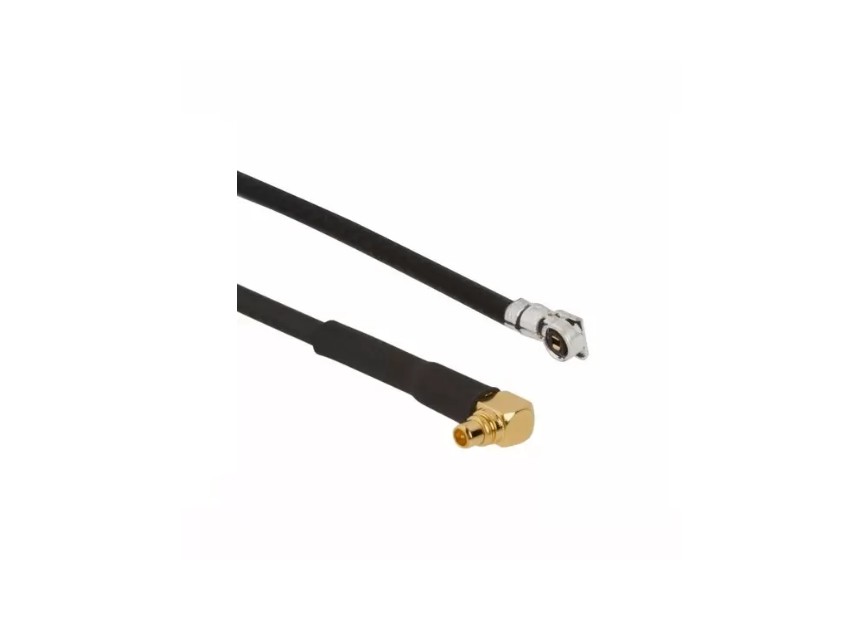
- Compatible with an array of miniature cable assemblies, offering design flexibility
Key Technical Details
- Impedance: 50 Ω
- Frequency: Up to 6 GHz (connector + cable dependent)
- Durable coupling for reliable connections under repeated use
- Precision brass construction with high-quality plating
- Ultra-compact footprint tailored for space-constrained designs
Applications
- Portable RF and spectrum monitoring devices
- Wireless diagnostic and testing equipment
- Telemetry, GPS and IoT gadgets
- Wearable and embedded RF electronics
- Cellular network maintenance tools
Explore our RP‑MMCX standard portfolio for dependable, miniature RF interconnects. Interested in customized cable types, plating, or unique performance needs? Contact us today to discuss tailored RP‑MMCX solutions.
Specifications
MMCX Connectors
Electrical
| Impedance | 50 Ohm |
| Frequency Range | DC - 6 GHz |
| Voltage Rating | 170 Volts RMS Continuous |
| Dielectric Withstanding Voltage | 500 VRMS Max |
| VSWR (Return Loss) | |
|
DC - 4 GHz
|
1.25 (-19 dB) Max |
|
4 - 6 GHz
|
1.40 (-16 dB) Max |
| Insulation Resistance | 500 MΩ Min |
| Center Contact Resistance | 10 mΩ Max |
| Outer Contact Resistance | 5 mΩ Max |
| Insertion Loss | .1 √(f(GHz)) dB Max |
| Power Handling | 63 W Max @ 1 GHz |
Environmental
| Temperature Range | −40°C to +90°C |
| Thermal Shock | MIL-STD-202, Method 107 |
| Corrosion | MIL-STD-202, Method 101 (Test Condition B) - 5% Salt Solution |
| Vibration | CECC 22000 4.6.3 |
| Mechanical Shock | MIL-STD-202, Method 213, Condition B |
| Moisture Resistance | MIL-STD-202, Method 103, Condition B |
Mechanical
| Mating Cycles
|
500 Min |
| Coupling Mechanism | Push-On |
| Interface Specification | CECC 22220 |
| Engagement Force | < 30 N |
| Disengagement Force | > 8 N @ 1 - 5 Mating Cycles
>4 N @ 100 - 500 Mating Cycles |
Note: These characteristics are typical and may not apply to all connectors.
Connector configurations may affect performance.
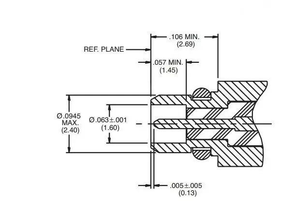
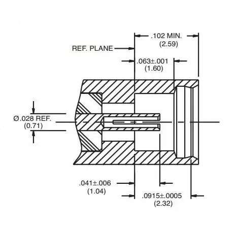
Interface Dimensions
Plug
Jack
Related Resources
.png)
Send us a Message
Please fill in the form below and we will contact you very soon.
Fields marked with an asterisk (*) are required.