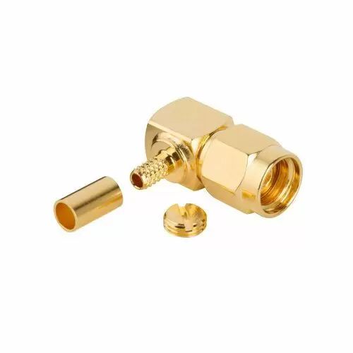
RP-SMA Connectors
Secure, reverse‑polarity SMA connectors delivering 50 Ω RF performance up to 18 GHz
Overview
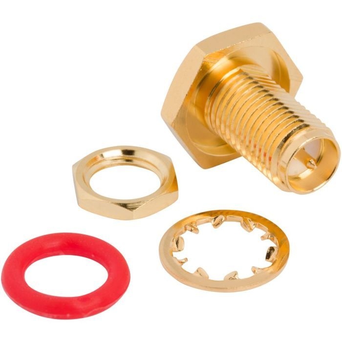
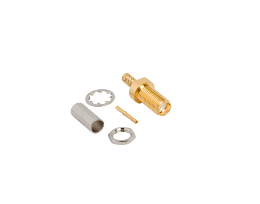
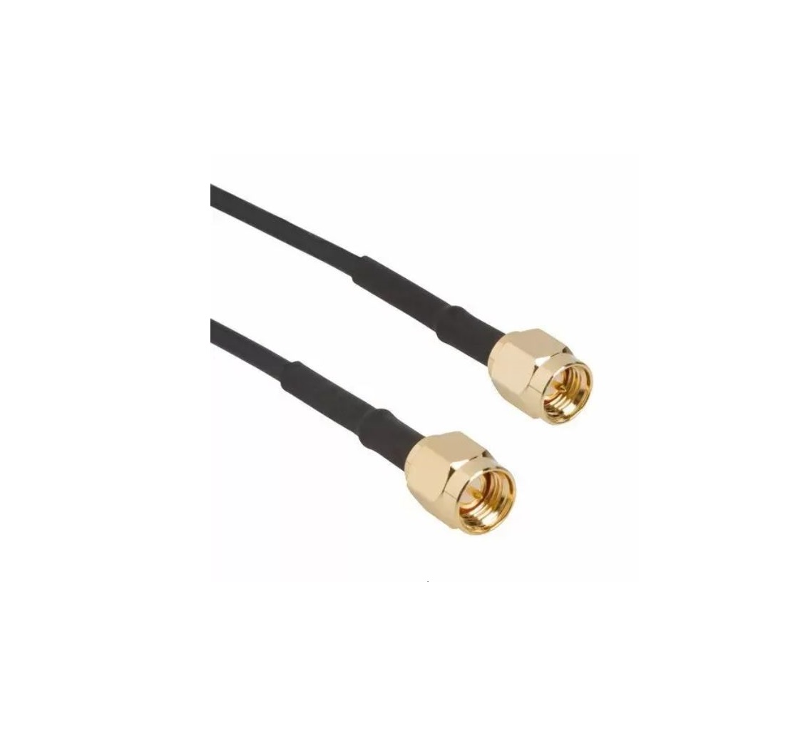
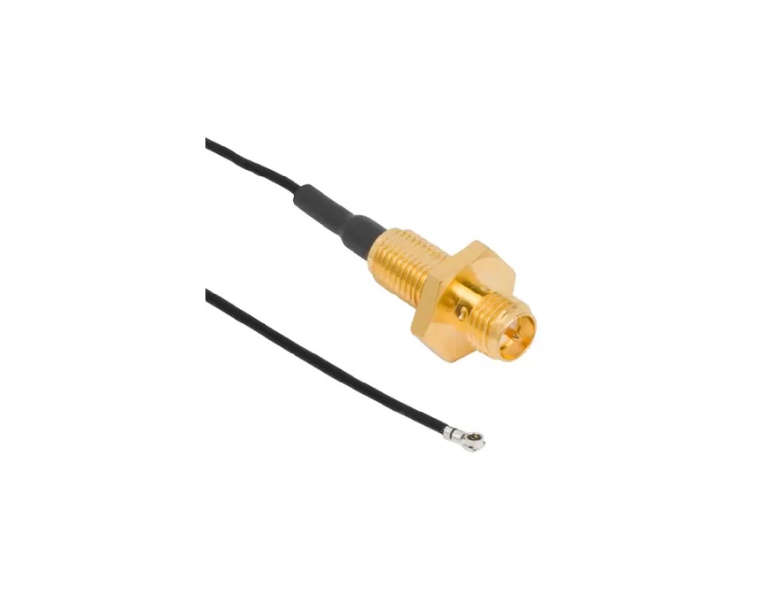
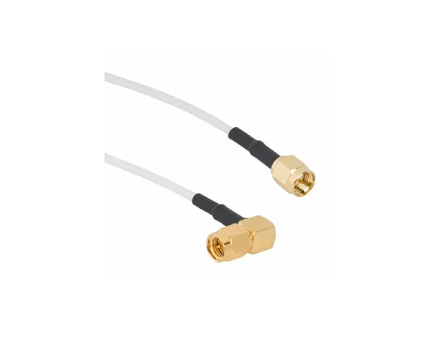
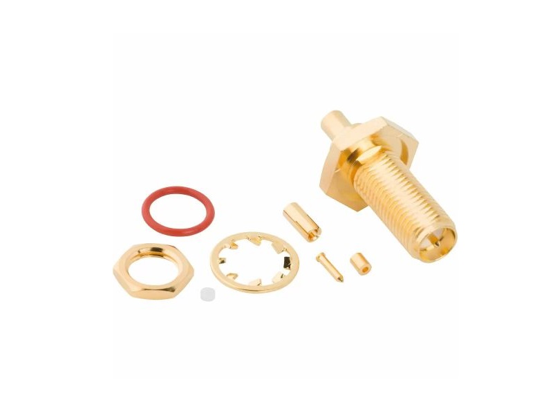
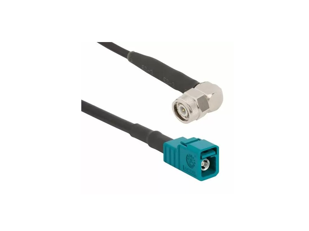
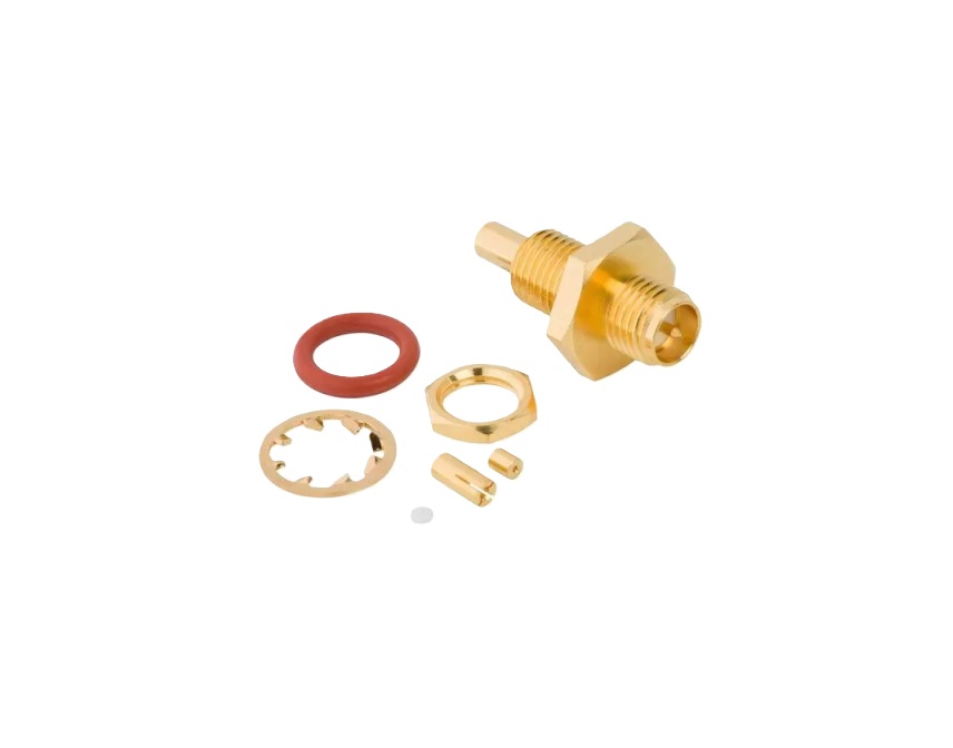
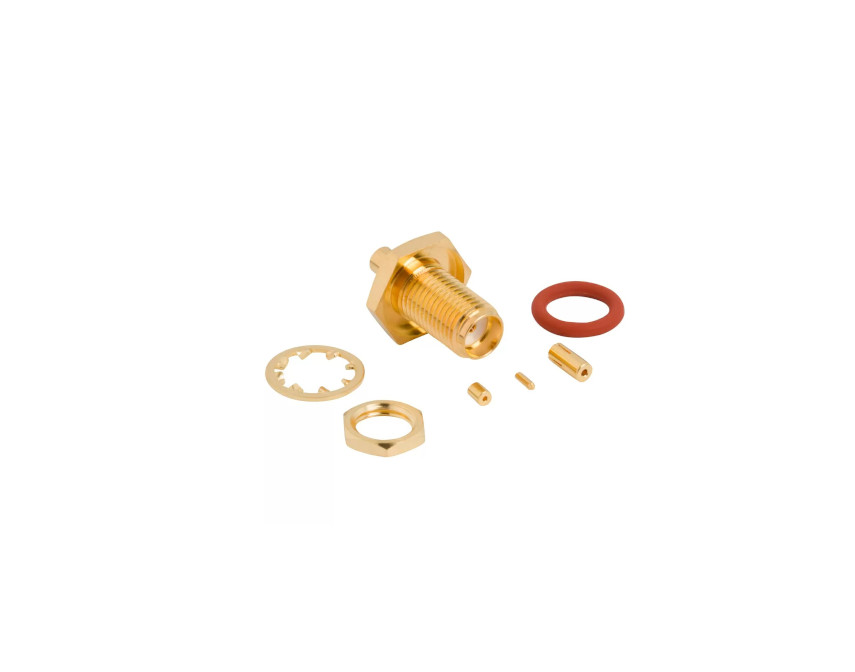
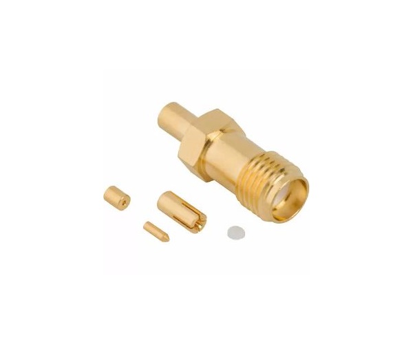
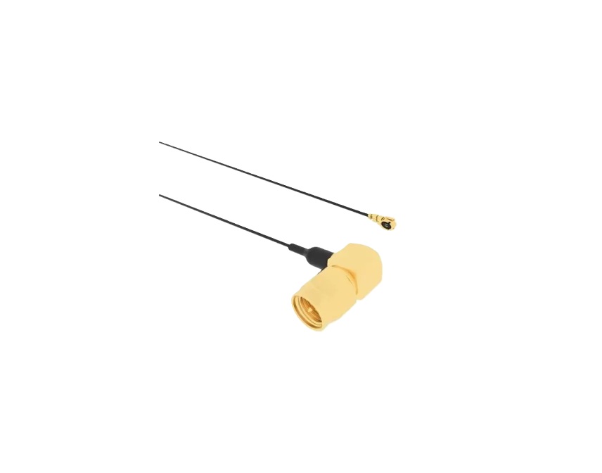
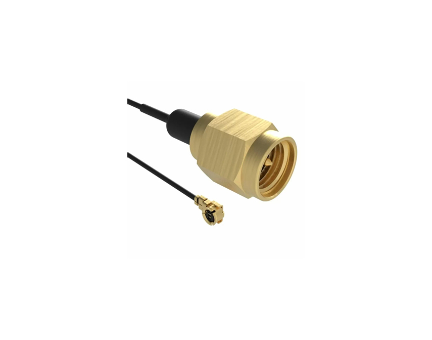
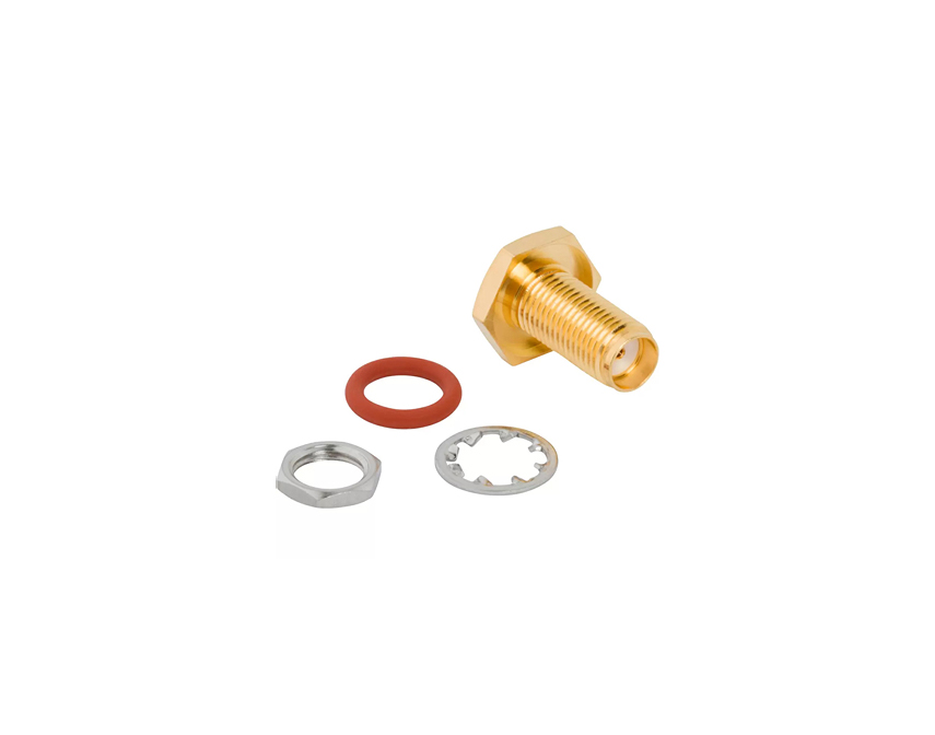
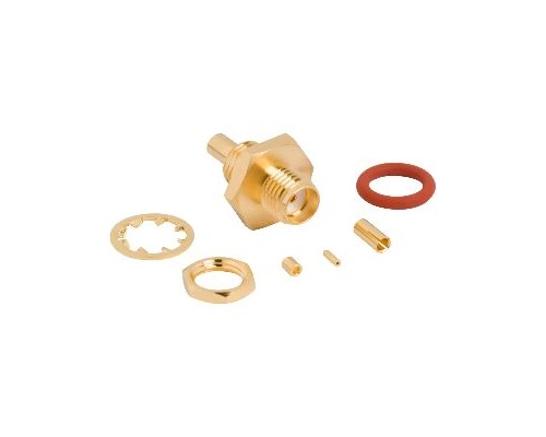
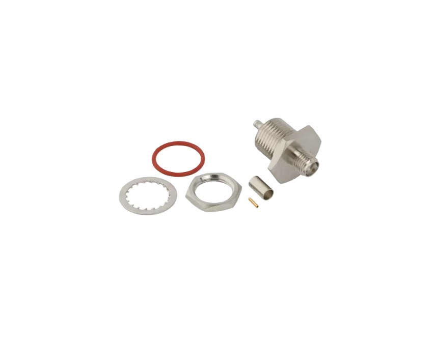
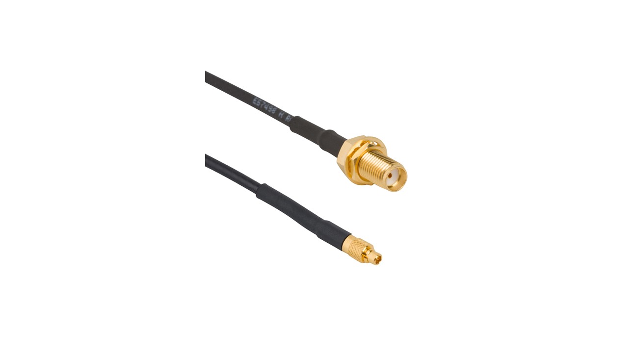
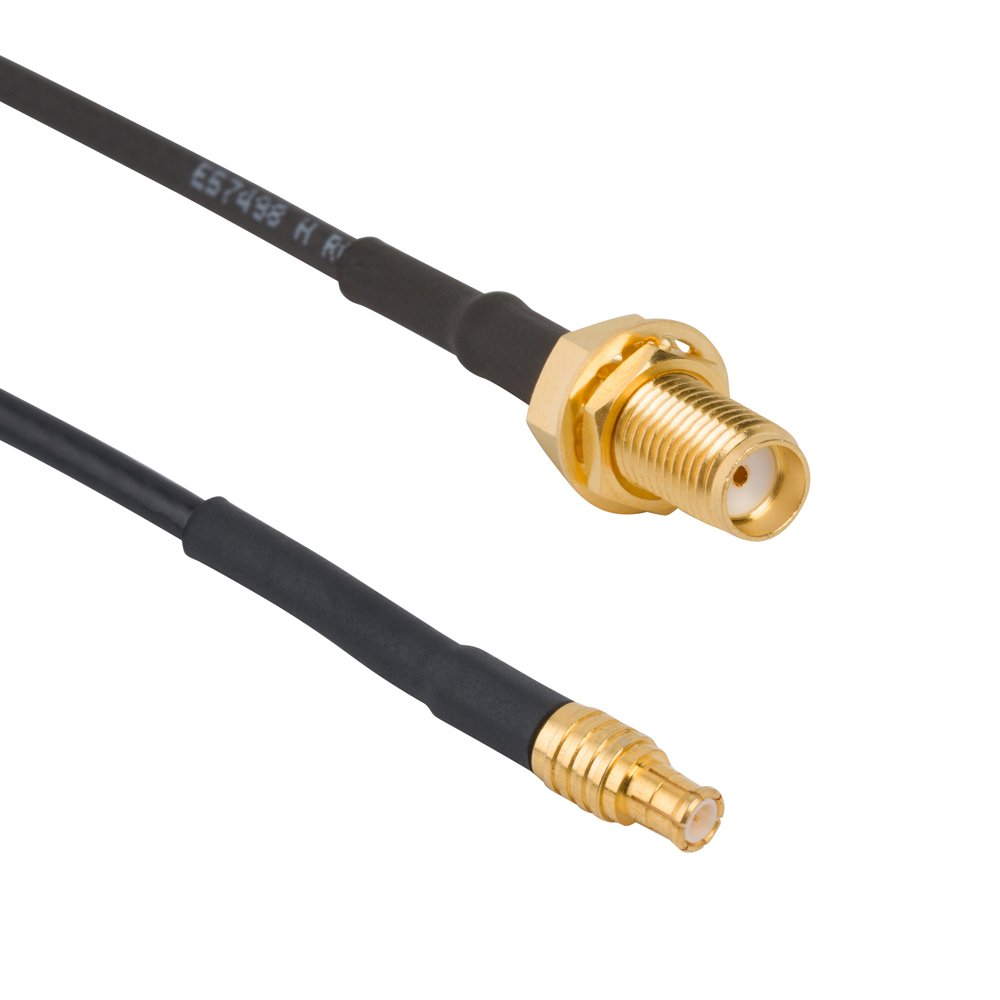
Amphenol RF’s RP‑SMA connectors are ideal for applications requiring compact, secure 50 Ω interfacing with reverse-polarity for added safety and regulatory compliance. These connectors maintain industry-standard electrical performance while featuring a reverse-polarity threaded interface to prevent unauthorized antenna attachments—perfect for wireless, Wi‑Fi and secure RF systems.
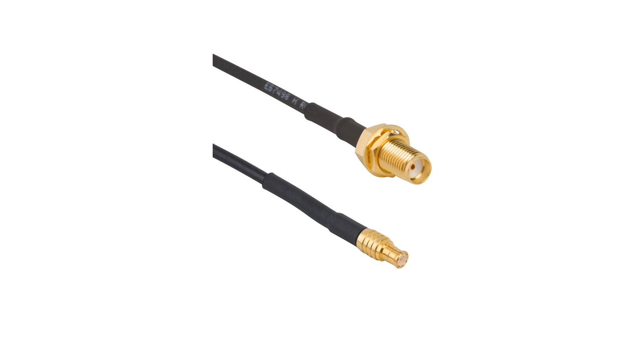
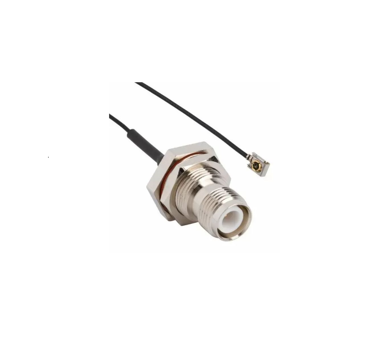
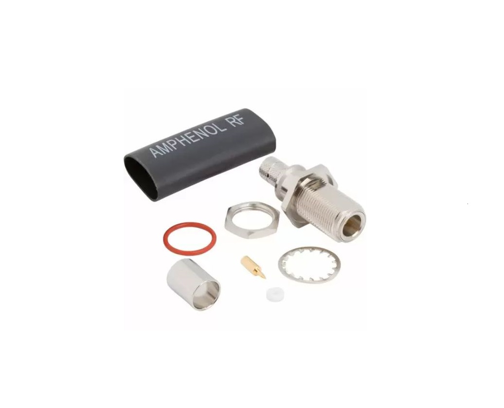
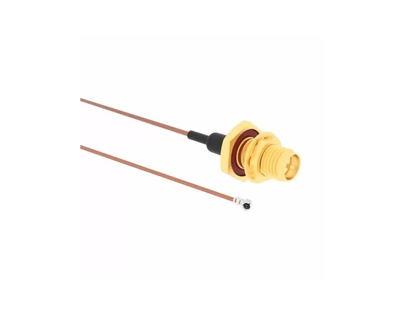
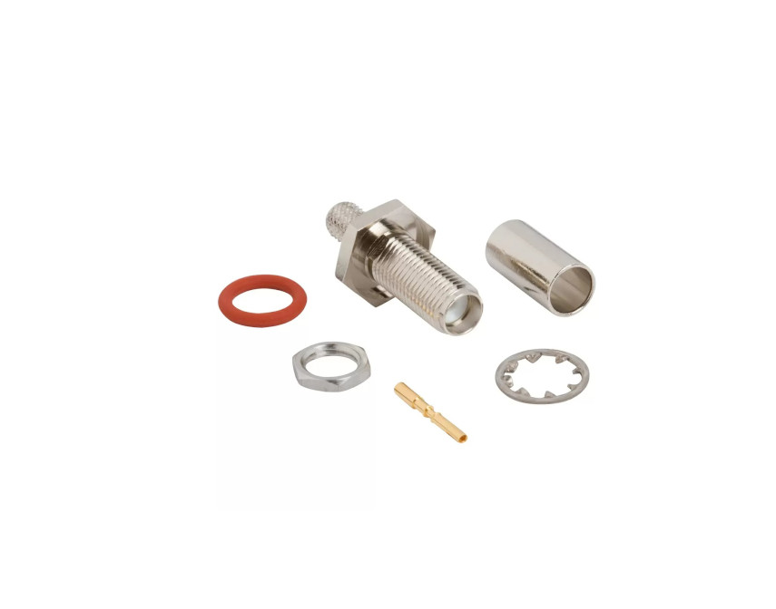
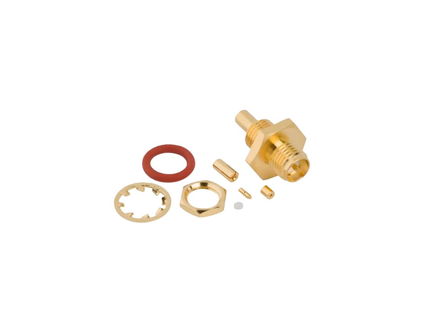
RP‑SMA cable assemblies undergo full hi-pot and continuity testing (excluding precision test cables). Standard configurations use heat-shrink tubing except when paired with microcoaxial cables. Though not hermetically sealed or Low‑PIM, IP67-rated bulkhead jacks provide rugged, weather-resistant options.
Features and Benefits
- Reverse-polarity interface prevents mismating and meets FCC antenna control needs
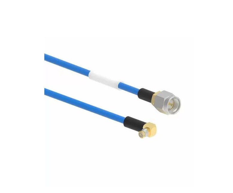
- Broadband performance from DC up to 18 GHz for diverse RF systems
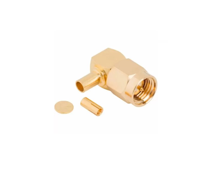
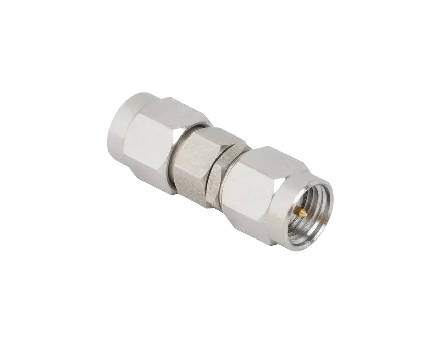
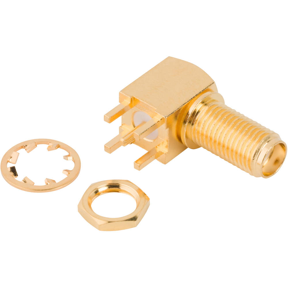
- Threaded coupling offers reliable, secure connections even in vibration-prone environments
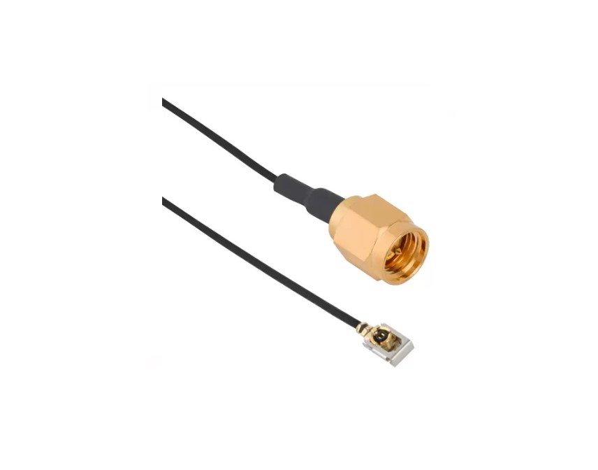
- Compatibility with standard SMA RF paths while enforcing RP interfaces
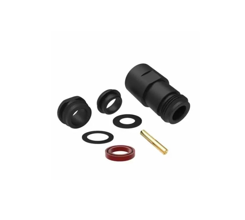
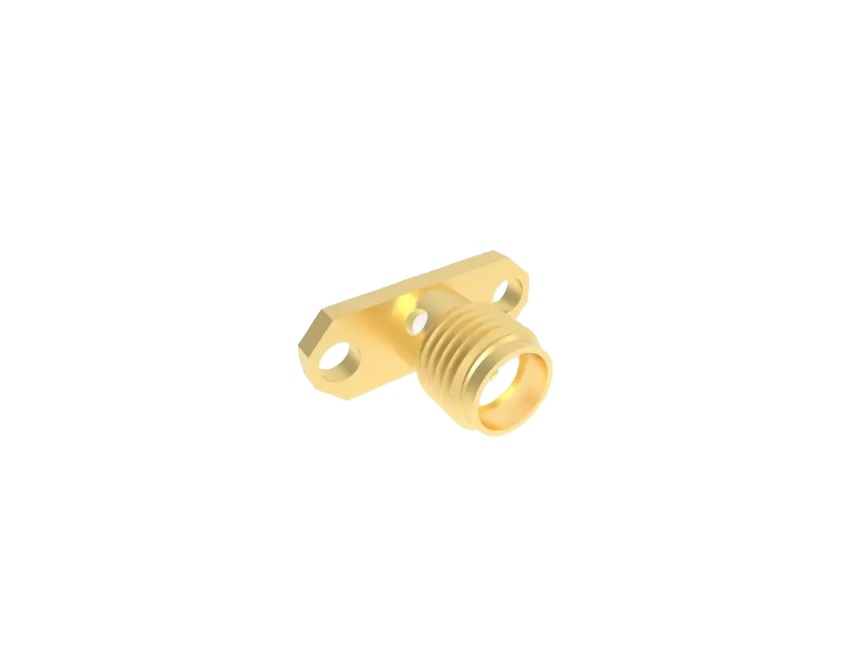
- IP67-rated bulkhead options for outdoor and harsh environment applications
Key Technical Details
- Impedance: 50 Ω
- Frequency Range: DC–18 GHz (accurate performance depends on cable type)
- Power Handling & Loss: Comparable to standard SMA; consult cable specs
- Coupling: Reverse-threaded, compact and secure
- Mechanical Durability: Typically rated for 500 mating cycles (depending on plating/material)
Applications
- Wi‑Fi routers, access points and regulatory-compliant wireless systems
- IoT devices and embedded wireless modules
- Antenna extension cables requiring RP interfaces
- Test and measurement equipment in need of secure cable retention
- Outdoor and portable electronics using IP67-rated connectors
RP‑SMA assemblies are hi-pot and continuity tested for reliability. Precision RP‑SMA test cables are sweep-tested and serialized.
Explore our range of standard RP‑SMA connectors or contact our engineering team for custom configurations tailored to your design requirements.
Specifications
SMA Connectors
Electrical
| Impedance | 50 Ohm |
| Frequency Range | DC - 18 GHz (Up to 34 GHz on Extended Range Designs) |
| Voltage Rating | 335 Volts RMS Continuous |
| Dielectric Withstanding Voltage | 1000 VRMS Min |
| VSWR (Return Loss) | |
|
M39012 Straight Connectors
|
|
|
.141" OD Copper Jacket Cable
|
1.05 + .005 f (GHz) |
|
RG-58/RG-142 Group
|
1.15 + .011 f (GHz) DC-12.4 GHz |
|
RG-174/RG-316 Group
|
1.15 + .02 f (GHz) DC-12.4 GHz |
|
RG-178 Group
|
1.20 + .025 f (GHz) DC-12.4 GHz |
|
M39012 Angle Connectors
|
|
|
.141" OD Copper Jacket Cable
|
1.10 + .01 f (GHz) |
|
RG-58/RG-142 Group
|
1.15 + .02 f (GHz) DC-12.4 GHz |
|
RG-174/RG-316 Group
|
1.15 + .03 f (GHz) DC-12.4 GHz |
|
RG-178 Group
|
1.20 + .03 f (GHz) DC-12.4 GHz |
| Insulation Resistance | 5000 MΩ Min |
| Center Contact Resistance | 3.0 mΩ Max |
| Outer Contact Resistance | 2.0 mΩ Max |
| RF Leakage | -60 dB Max (DC - 3 GHz) |
| Insertion Loss | .06 √(f(GHz)) dB Max |
| Power Handling | 75 W @ 10 GHz @ 25ºC |
Environmental
| Temperature Range | |
|
Typical
|
-65°C to +165°C |
|
Styrene Insulator or Phosphor Bronze Contact
|
-40°C to +85°C |
| Thermal Shock | MIL-STD-202, Method 107 (Test Condition B) except high temp test @ +200°C |
| Corrosion | MIL-STD-202, Method 101 (Test Condition B) - 5% Salt Solution |
| Vibration | MIL-STD-202, Method 204 (Test Condition D) |
| Mechanical Shock | MIL-STD-202, Method 213 (Test Condition I) - No Discontinuity Permitted |
| Moisture Resistance | MIL-STD-202, Method 106 |
| Altitude | MIL-STD-202, Method 105 (Test Condition C) |
Mechanical
| Mating Cycles | 500 Min |
| Coupling Mechanism | Threaded |
| Interface Specification | MIL-STD-348 |
| Mating Torque (Stainless Steel Plug) | 0.8 - 1.1 N-m (7 - 10 in-lbs) |
| Mating Torque (Brass Plug) | 0.3 - 0.6 N-m (3 - 5 in-lbs) |
Note: These characteristics are typical and may not apply to all connectors.
Connector configurations may affect performance.
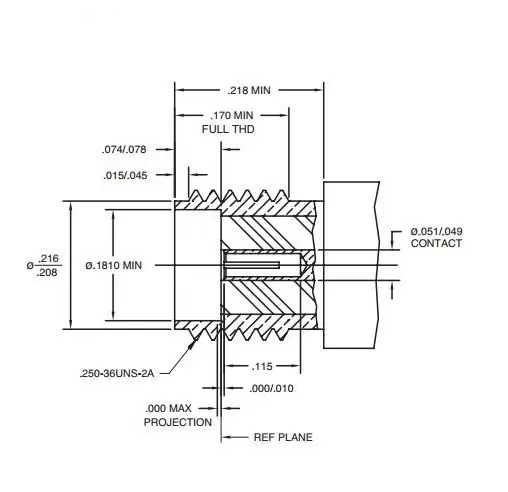
Interface Dimensions
Plug
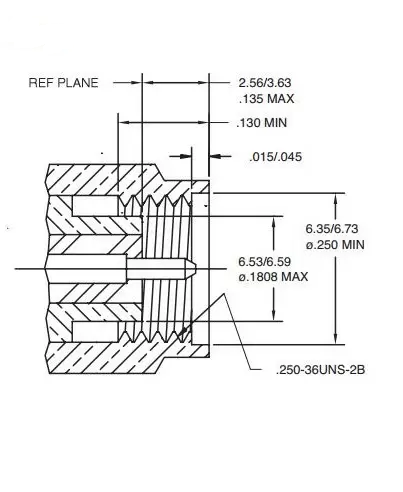
Jack
Related Resources

.png)
.jpg)
.png)
.png)


Send us a Message
Please fill in the form below and we will contact you very soon.
Fields marked with an asterisk (*) are required.