RP-SMB Connectors
Compact, snap-on RF interface for 50 Ω cable systems
Overview
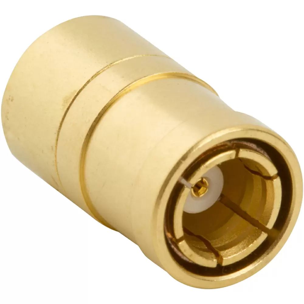
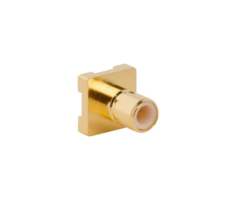
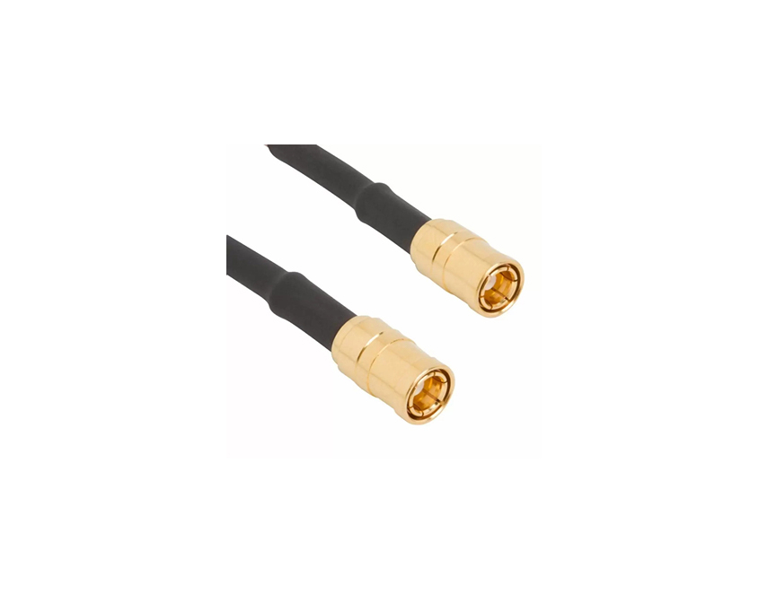
Amphenol RF’s RP‑SMB connectors provide reliable, space-efficient snap‑on connections designed for reverse‑polarity RF applications. Engineered to meet industry standards, this series ensures compatibility across a wide range of coaxial cable types while maintaining signal integrity. Common in wireless equipment and instrumentation, RP‑SMB offers a convenient solution without the bulk of larger threaded connectors.
These connectors are ideal for designers seeking a low-profile, reverse-polarity option with dependable electrical performance up to 4 GHz. Whether used in handheld devices, portable WLAN systems, or automated test setups, they deliver quick-connect convenience with consistent 50 Ω impedance.
Features and Benefits
- Reverse-polarity SMB interface (RP‑SMB) avoids accidental mating with standard SMB
- 50 Ω impedance ensures signal consistency across frequency-critical systems
- Snap-on coupling allows fast, tool-free installation and removal
- Broad cable compatibility (RG‑174, RG‑188A, RG‑316, etc.)
- Compact footprint fits tight applications in wireless and test equipment
Key Technical Details
- Impedance: 50 Ω
- Frequency range: DC–4 GHz (cable‑dependent)
- Mating cycles: Snap‑on design supports multiple connect/disconnect operations
- Temperature range: −65 °C to +165 °C (material/cable dependent)
- Voltage rating: Suitable for standard RF use (per MIL‑C‑39012 compliance)
Applications
- Wireless LAN and RF test systems
- Portable radio and communication devices
- Automated test equipment and instrumentation
- OEM wireless modules and specialty RF interfaces
Browse our standard RP‑SMB connector range to find configurations that meet your requirements. For custom lengths, cable types, or tailored termination styles, contact our applications engineering team for personalized support.
Specifications
SMB Connectors
Electrical
| Impedance | 50 Ohm |
| Frequency Range | DC - 4 GHz (DC - 10 GHz on Extended Range Designs) |
| Voltage Rating | 335 Volts RMS Continuous |
| Dielectric Withstanding Voltage | 1000 VRMS Max |
| VSWR (Return Loss) | |
RG-178/RG-196 Group |
|
Straight Connectors |
1.30 + .04 f (GHz) |
Right Angle Connectors |
1.45 + .06 f (GHz) |
RG-174/RG-316/RG-188 Group |
|
Straight Connectors |
1.25 + .04 f (GHz) |
Right Angle Connectors |
1.35 + .04 f (GHz) |
| Insulation Resistance | 1000 MΩ Min |
| Center Contact Resistance | 6 mΩ Max |
| Outer Contact Resistance | 1 mΩ Max |
| RF Leakage | -120 dB Max (DC - 3 GHz) |
| Insertion Loss | |
Straight Connectors |
.30 dB @ 1.5 GHz Max |
Right Angle Connectors |
.60 dB @ 1.5 GHz Max |
| Power Handling | 95 W @ 1 GHz @ 25ºC |
Environmental
| Temperature Range | −65°C to +165°C |
| Thermal Shock | MIL-STD-202 Method 107 (Test Condition B) except high temp test @ +200⁰C |
| Corrosion | MIL-STD-202 Method 101 (Test Condition B) 5% Salt Solution |
| Vibration | MIL-STD-202 Method 204, snap on (Test Condition B) (15G's) |
| Mechanical Shock | MIL-STD-202 Method 213, snap on (Test Condition B) 75 G's @ 6 milliseconds 1/2 sine |
| Moisture Resistance | MIL-STD-202 Method 106 |
| Altitude | MIL-STD-202 Method 105 (Test Condition C) |
Mechanical
| Mating Cycles | 500 Min |
| Coupling Mechanism | Snap-On |
| Interface Specification | MIL-STD-348 |
| Engagement Force | 14 lbs (62 N) Max |
| Disengagement Force | 2 lbs (8.9 N) Max |
Note: These characteristics are typical and may not apply to all connectors.
Connector configurations may affect performance.
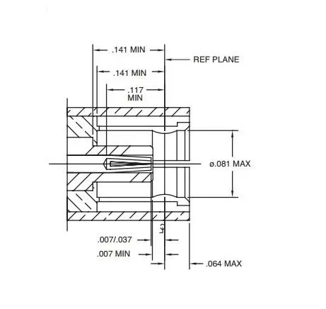
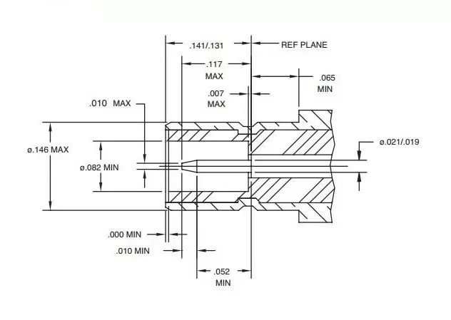
Interface Dimensions
Plug
Jack
Related Resources

Send us a Message
Please fill in the form below and we will contact you very soon.
Fields marked with an asterisk (*) are required.