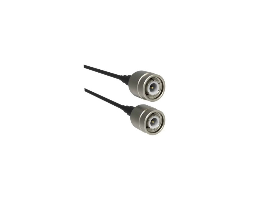
RP-TNC Connectors
Reliable, threaded reverse‑polarity RF connectors for secure, weather‑resistant applications
Overview
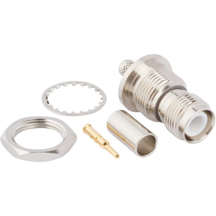
Amphenol RF’s RP‑TNC connectors bring the durability and performance of standard TNC interfaces to applications requiring reverse‑polarity for enhanced tamper resistance and regulatory compliance. Their threaded coupling ensures a secure connection with excellent resistance to vibration and environmental exposure—making them a reliable RF interface.
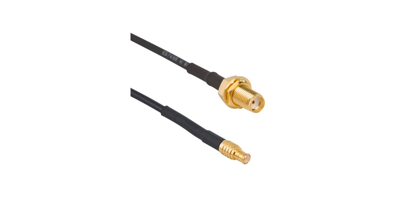
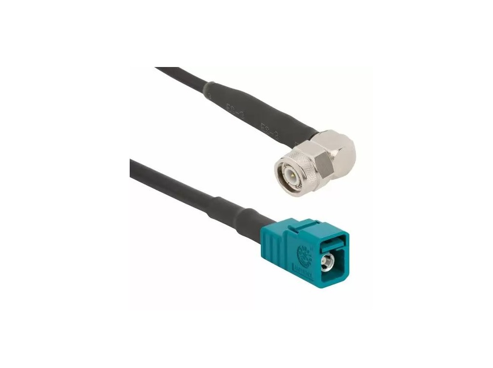
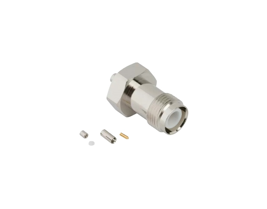
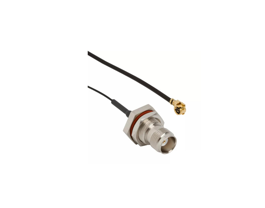
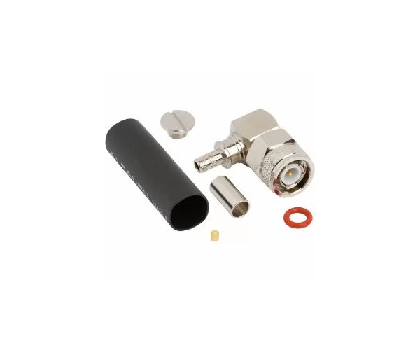
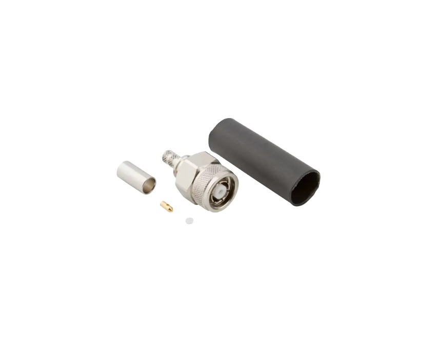
With compatibility to operate from DC up to 11 GHz (18 GHz for extended-range designs), RP‑TNCs support demanding wireless, industrial and outdoor applications. A full lineup—including straight and right-angle plugs, panel-mount jacks and IP67-rated microcoax versions—ensures flexible deployment across systems.
Features and Benefits
- Reverse‑polarity interface—prevents mating with standard TNCs
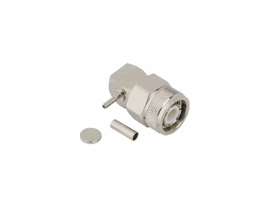
- Threaded coupling—vibration-resistant and secure
- Durable construction—brass bodies, beryllium copper contacts
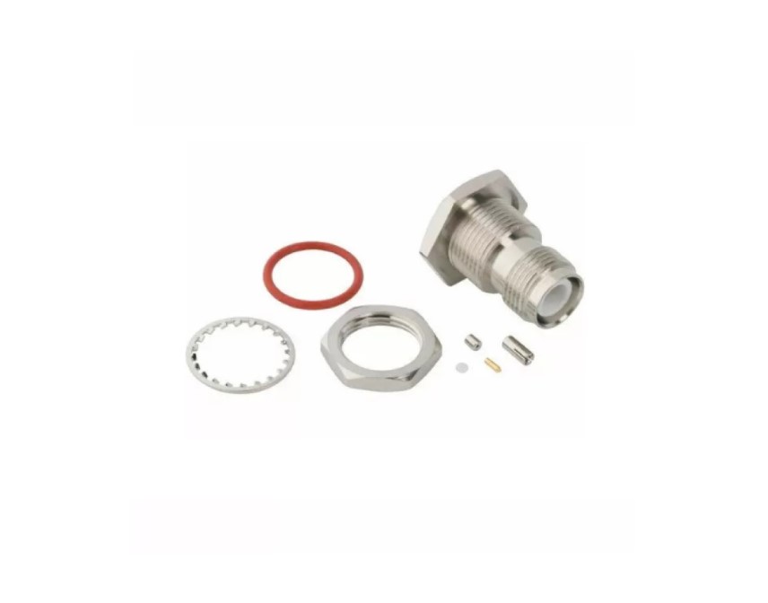
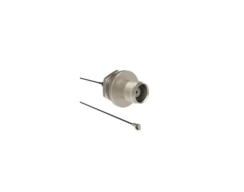
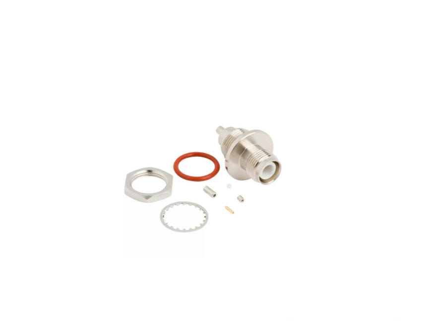
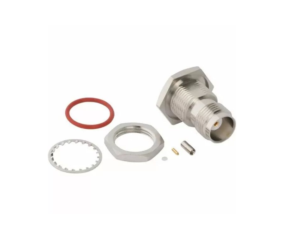
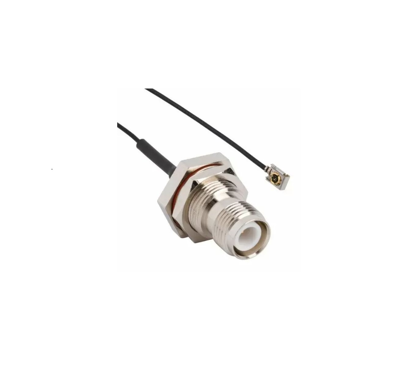
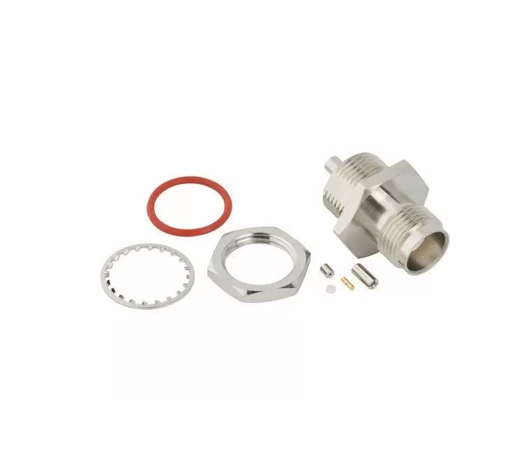
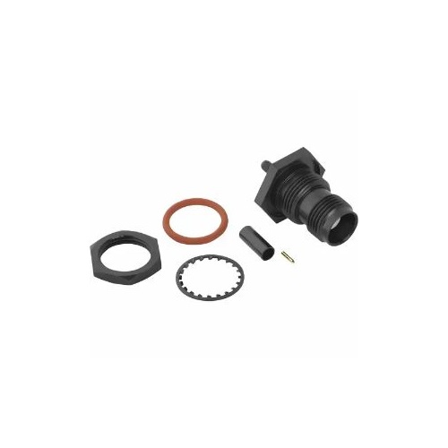
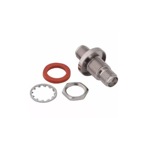
- Versatile configurations—straight, right-angle, panel-mount, IP67
- Wide cable compatibility—micro‑coax (0.81, 1.32, 1.37 mm), LMR, RG types
Key Technical Details
- 50 Ω impedance
- Frequency range DC to 11 GHz (up to 18 GHz for extended-range models)
- Reverse-polarity male has female-style contact and vice versa
- Available in IP67-rated designs with microcoax compatibility
Applications
- Antennas and base stations
- Industrial and outdoor wireless systems
- Heavy equipment and vehicular communications
- Security, surveillance and tamper-sensitive installations
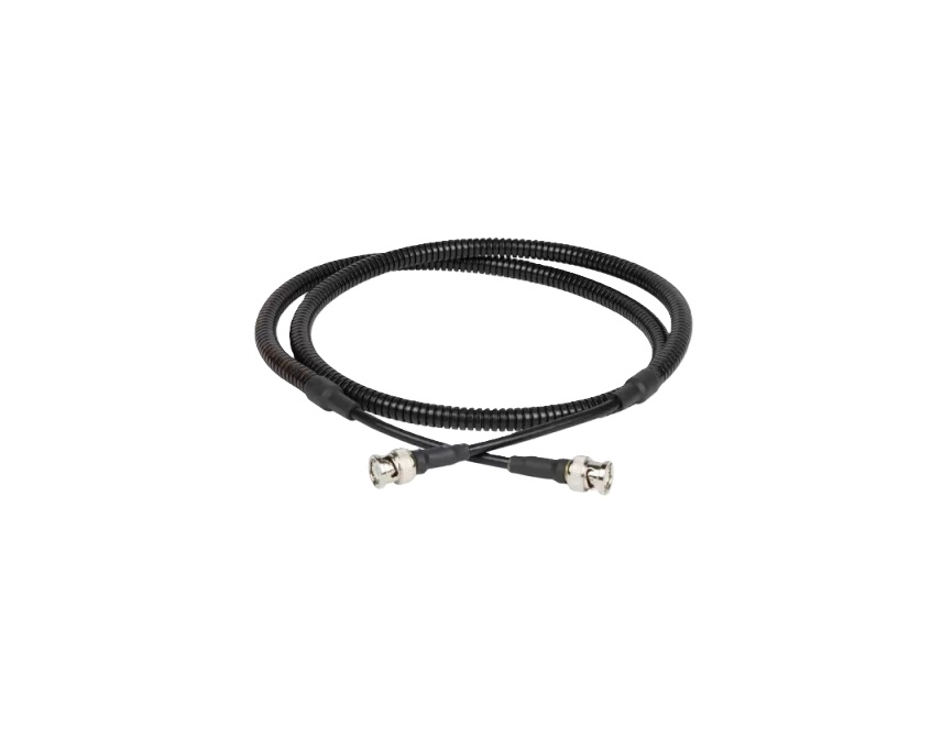
Explore our standard RP‑TNC cable assemblies below. Contact our engineering team for custom solutions—whether you need alternative cable types, unique panel configurations, or specialized IP67-rated designs.
Specifications
TNC Connectors
Electrical
| Impedance | 50 Ohm |
| Frequency Range | DC - 11 GHz (DC - 18 GHz on Extended Range Designs) |
| Voltage Rating | 500 Volts Peak |
| Dielectric Withstanding Voltage | 1500 VRMS Max |
| VSWR (Return Loss) | |
DC - 11 GHz |
1.3 (-18 dB) Max |
| Insulation Resistance | 5000 MΩ Min |
| Center Contact Resistance | 1.5 mΩ Max |
| Outer Contact Resistance | 0.2 mΩ Max |
| RF Leakage | -60 dB Max @ 3 GHz |
| Insertion Loss | |
M39012 Straight Connectors |
0.18 dB Max @ 9 GHz |
M39012 Right Angle Connectors |
0.21 dB Max @ 9 GHz |
| Power Handling | 316 W @ 1 GHz @ 25 ºC |
Environmental
| Temperature Range | −65°C to +165°C |
| Thermal Shock | MIL-STD-202, Method 107 (Test Condition B) except high temp test @ +200⁰C |
| Corrosion | MIL-STD-202, Method 101 (Test Condition B) - 5% Salt Solution |
| Vibration | MIL-STD-202, Method 204 (Test Condition B) |
| Mechanical Shock | MIL-STD-202, Method 213 (Test Condition G) - No Discontinuity Permitted |
| Moisture Resistance | MIL-STD-202, Method 106 |
| Altitude | MIL-STD-202 Method 105 (Test Condition C) |
Mechanical
| Mating Cycles | 500 Min |
| Coupling Mechanism | Threaded |
| Interface Specification | MIL-STD-348 |
| Mating Torque | 4 - 6 inch-pounds (0.51 - 0.67 N-m) |
Note: These characteristics are typical and may not apply to all connectors.
Connector configurations may affect performance.
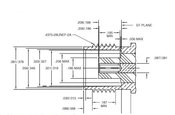
Interface Dimensions
Plug
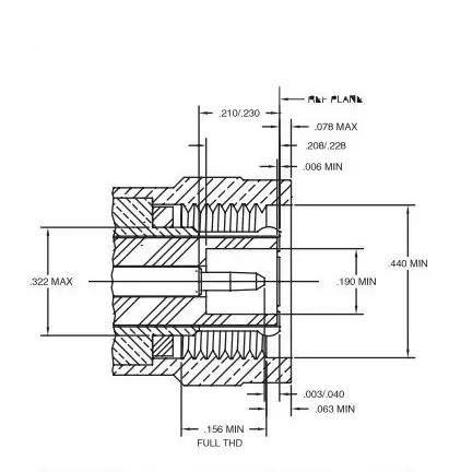
Jack
Related Resources

.png)


")

Send us a Message
Please fill in the form below and we will contact you very soon.
Fields marked with an asterisk (*) are required.