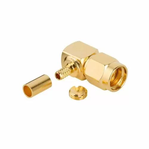
SMA Connectors
Versatile 50 Ω threaded RF interconnects from DC to 18 GHz in compact designs
Overview
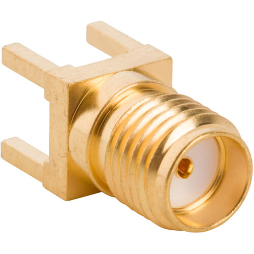
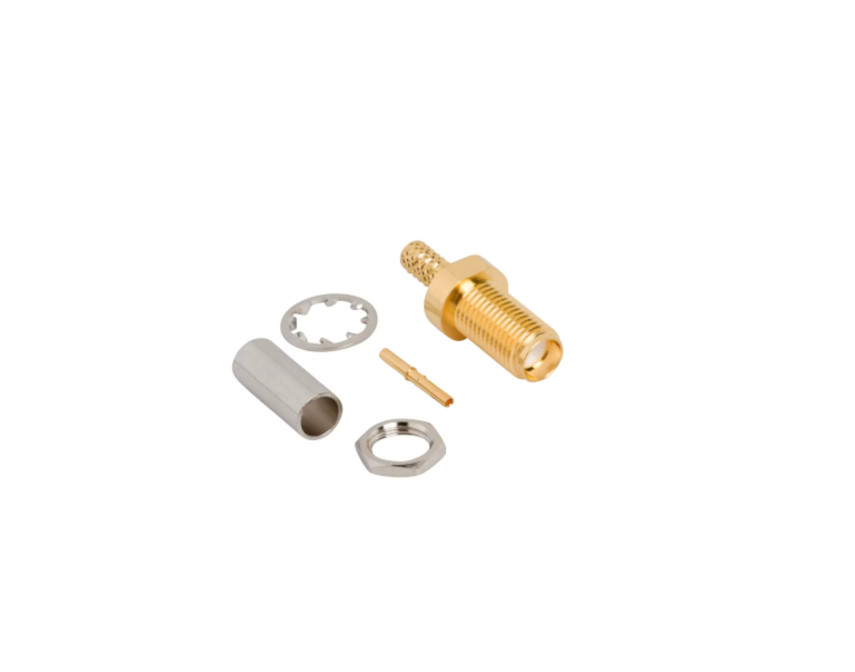
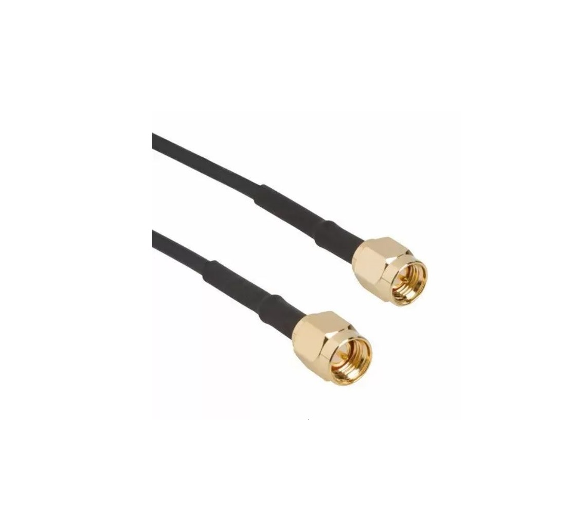
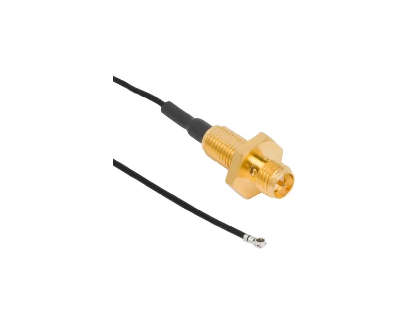
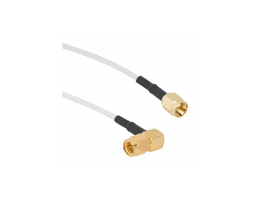
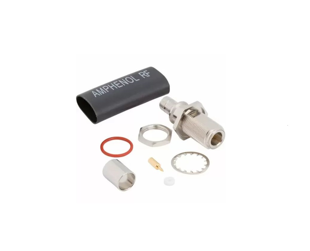
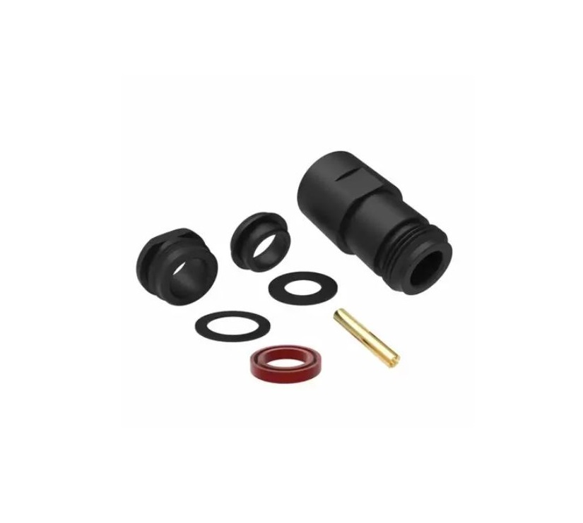
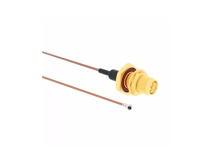
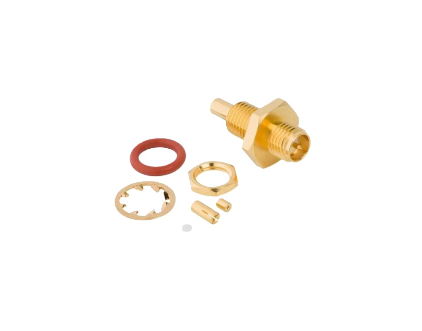
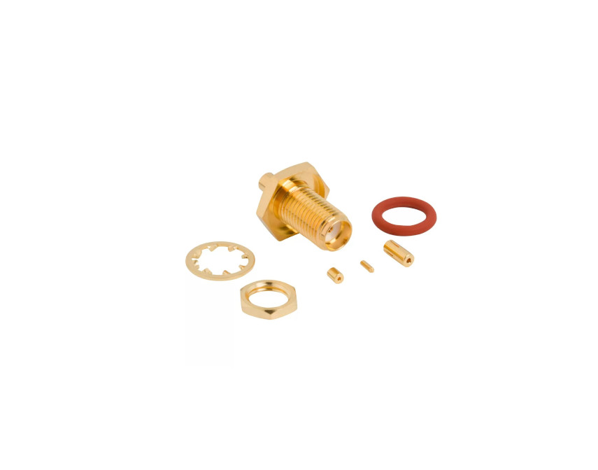
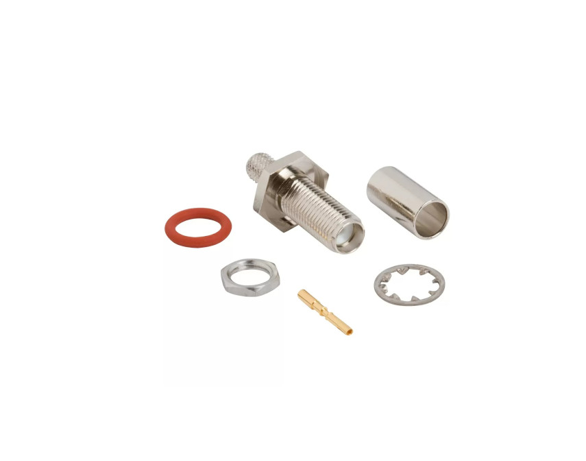
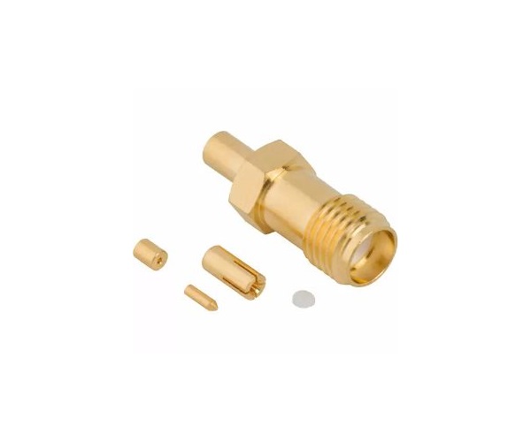
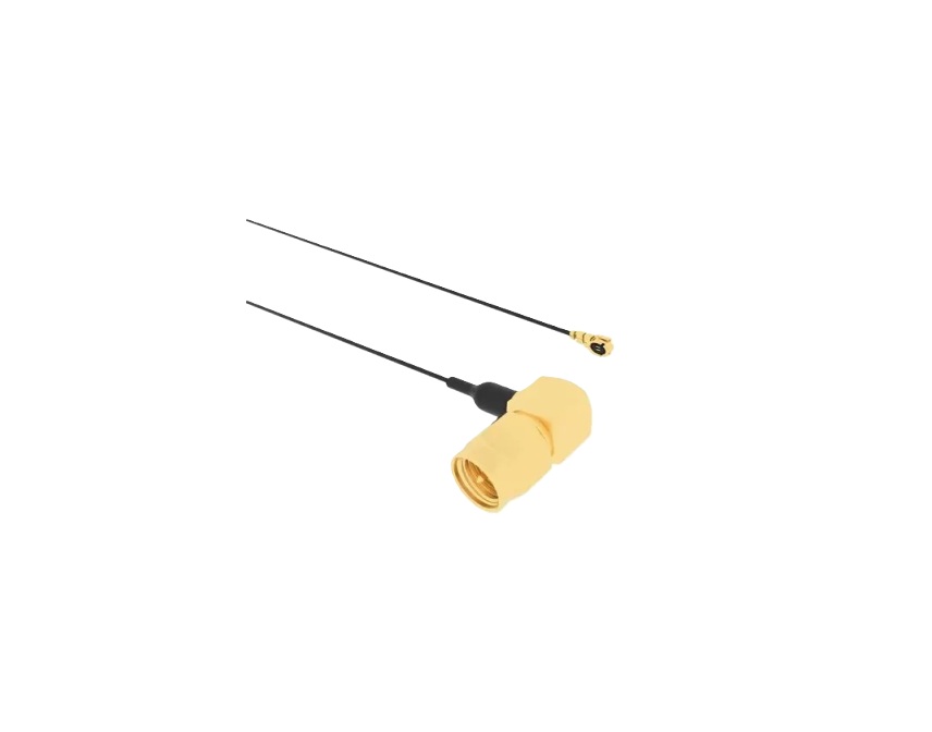
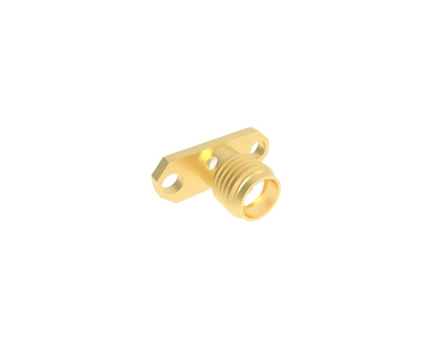
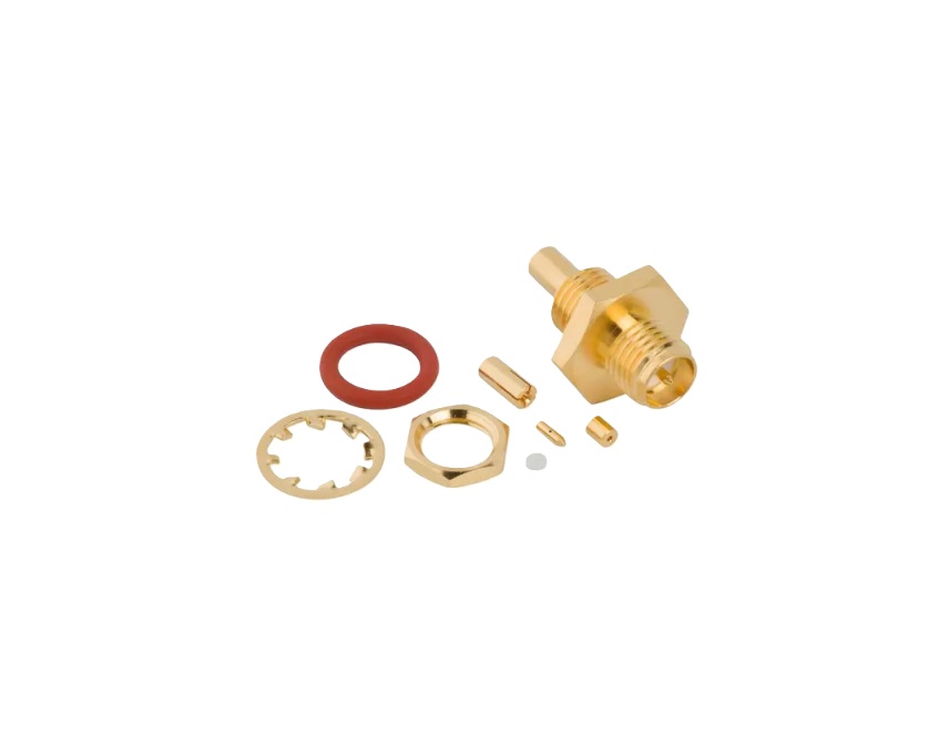
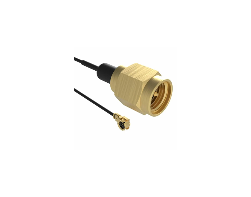
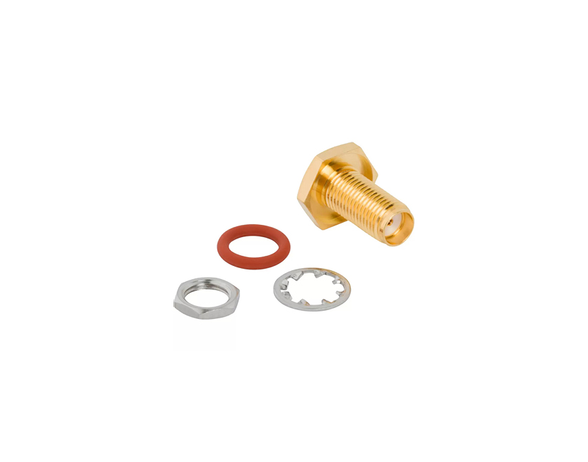
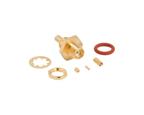
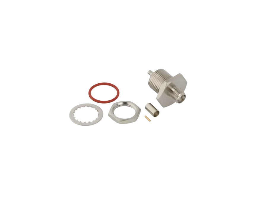
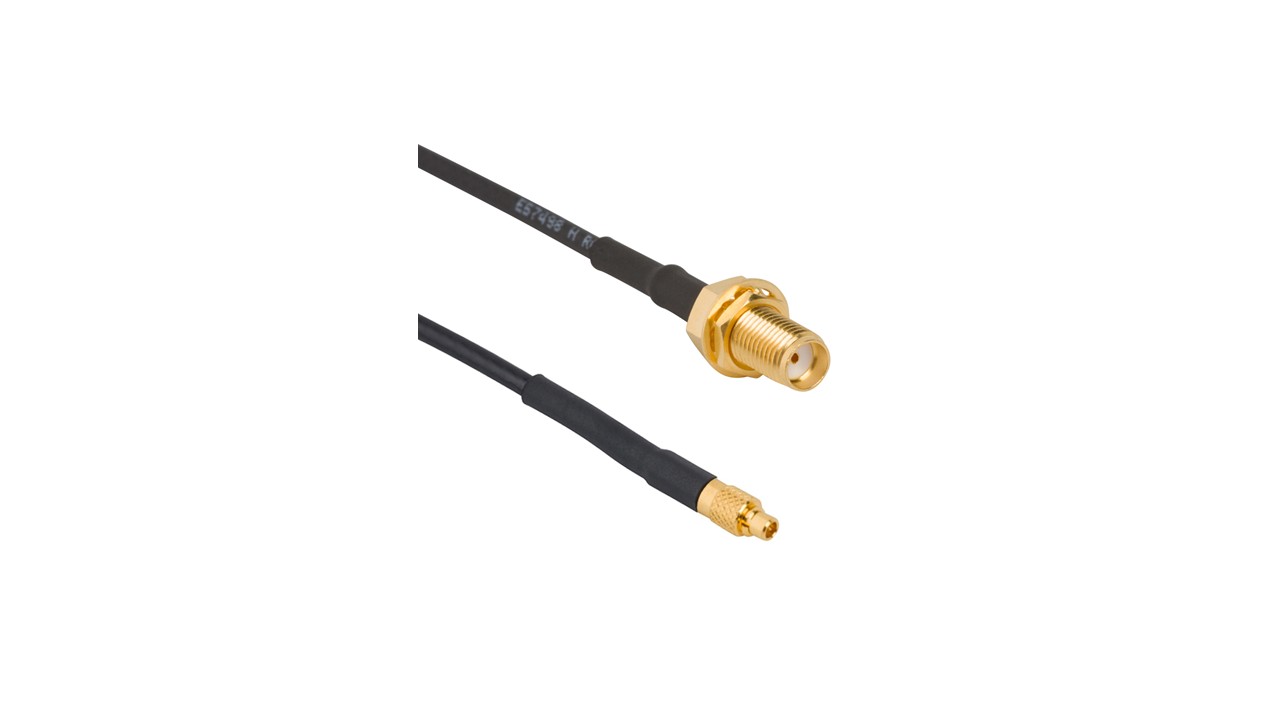
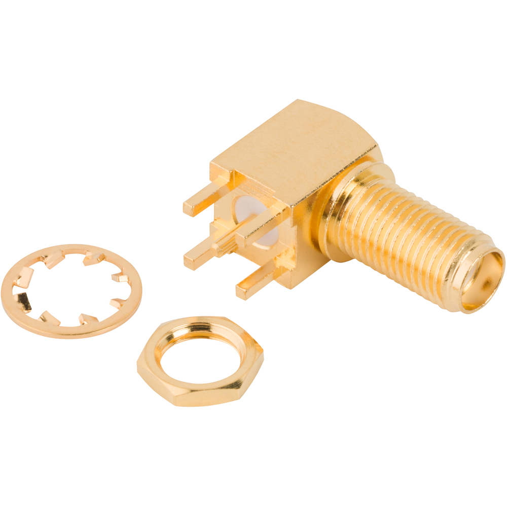
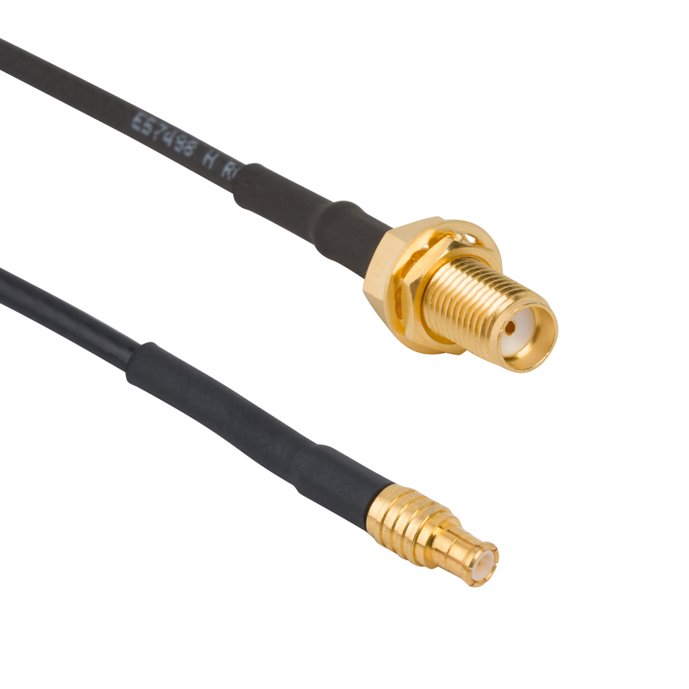
Amphenol RF’s SMA connectors deliver precision RF performance with durable threaded coupling for applications ranging from wireless infrastructure to test instrumentation. Crafted in stainless steel or brass per MIL‑C‑39012 standards, SMA interfaces provide repeatable contact, excellent phase stability and compatibility with industry-standard cables, semi‑rigid and LM(R) series.
Designed to handle up to 34 GHz in extended‑range versions, SMA connectors are trusted in portable radios, radar systems, aerospace and precision test solutions where signal integrity is paramount and mechanical ruggedness is essential.
Features and Benefits
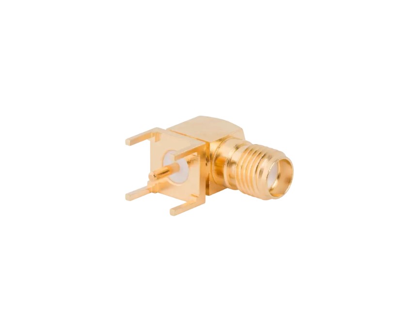
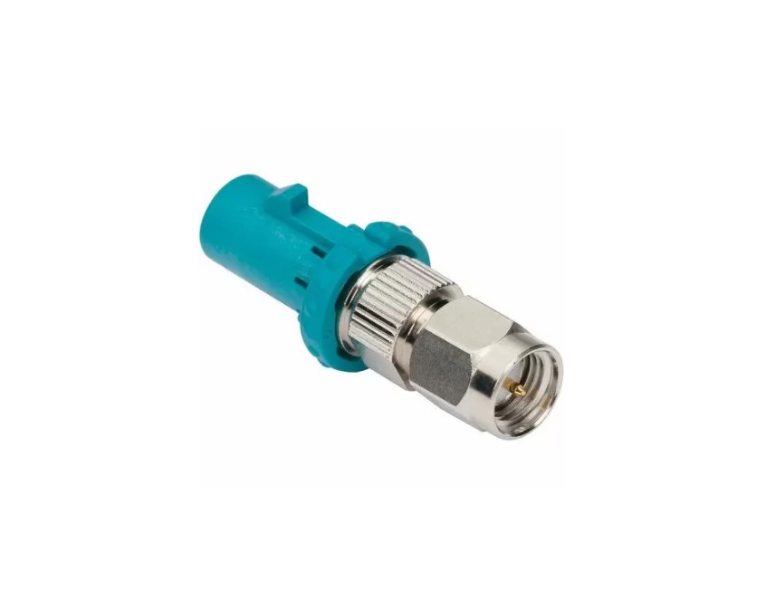
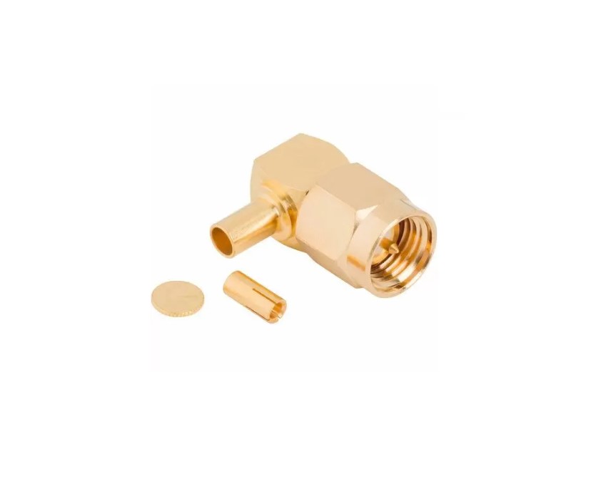
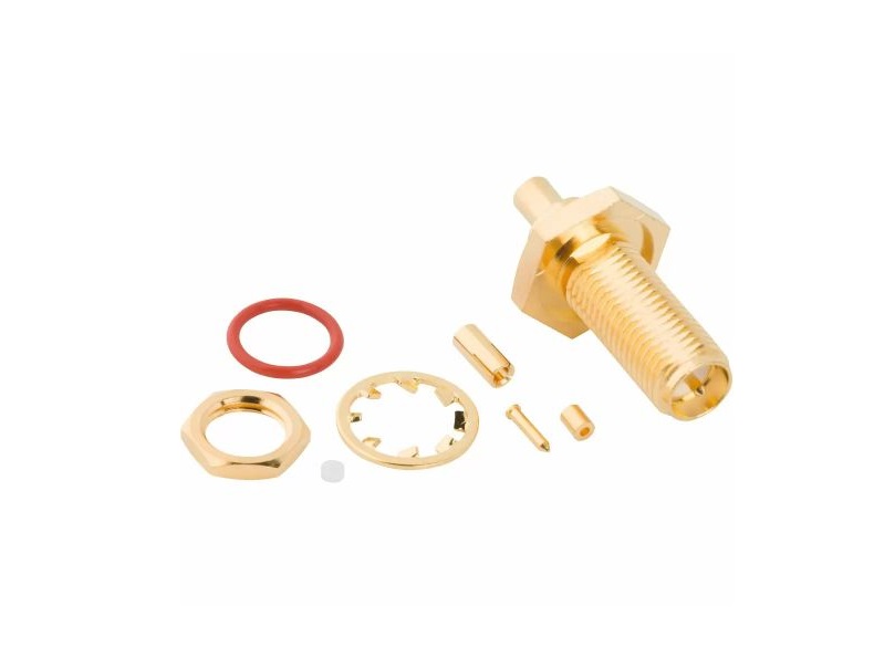
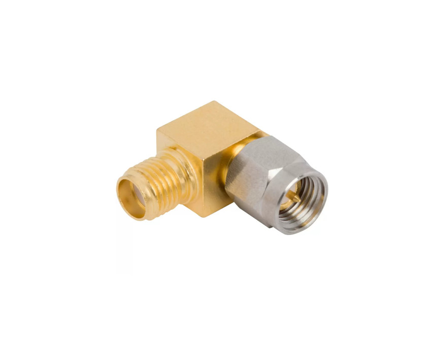
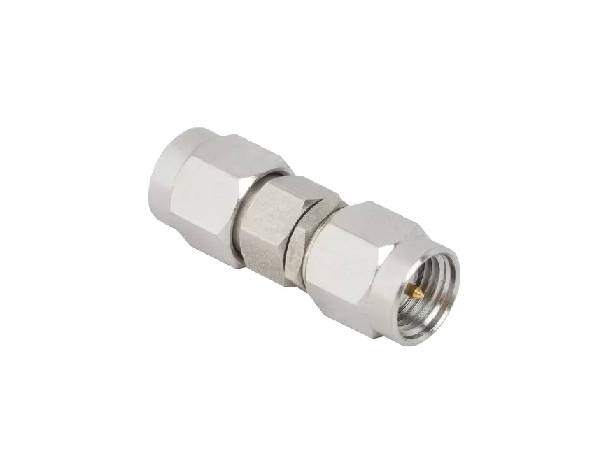
- Precision ¼‑36 threaded coupling for robust vibration resistance
- Frequency range DC–18 GHz (up to 34 GHz extended‑range)
- High durability: up to 500 mating cycles
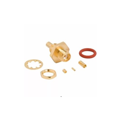
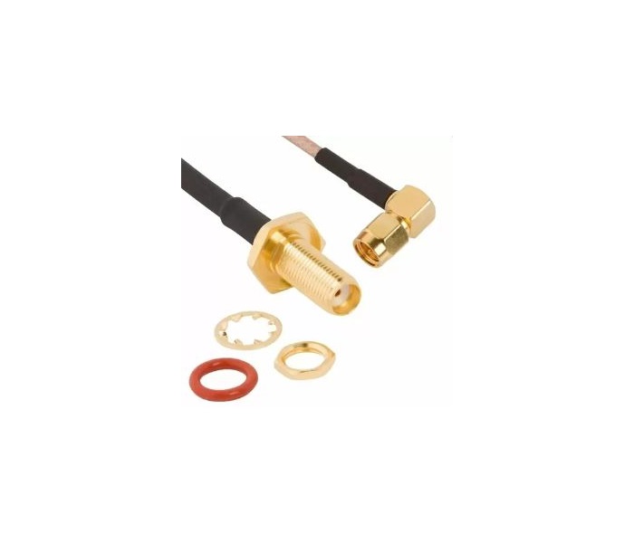
- Materials: stainless steel or brass, gold/nickel/passivated finishes
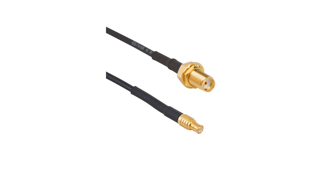
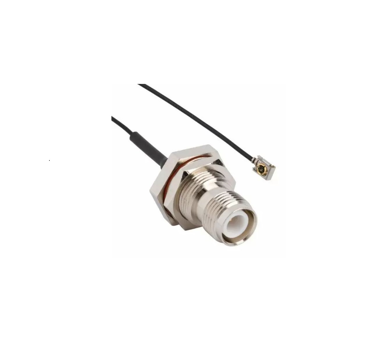
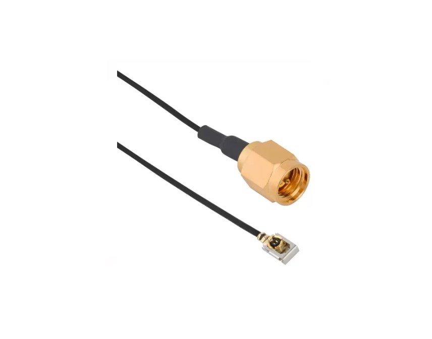
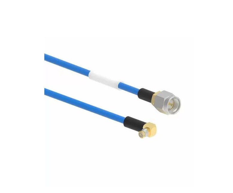
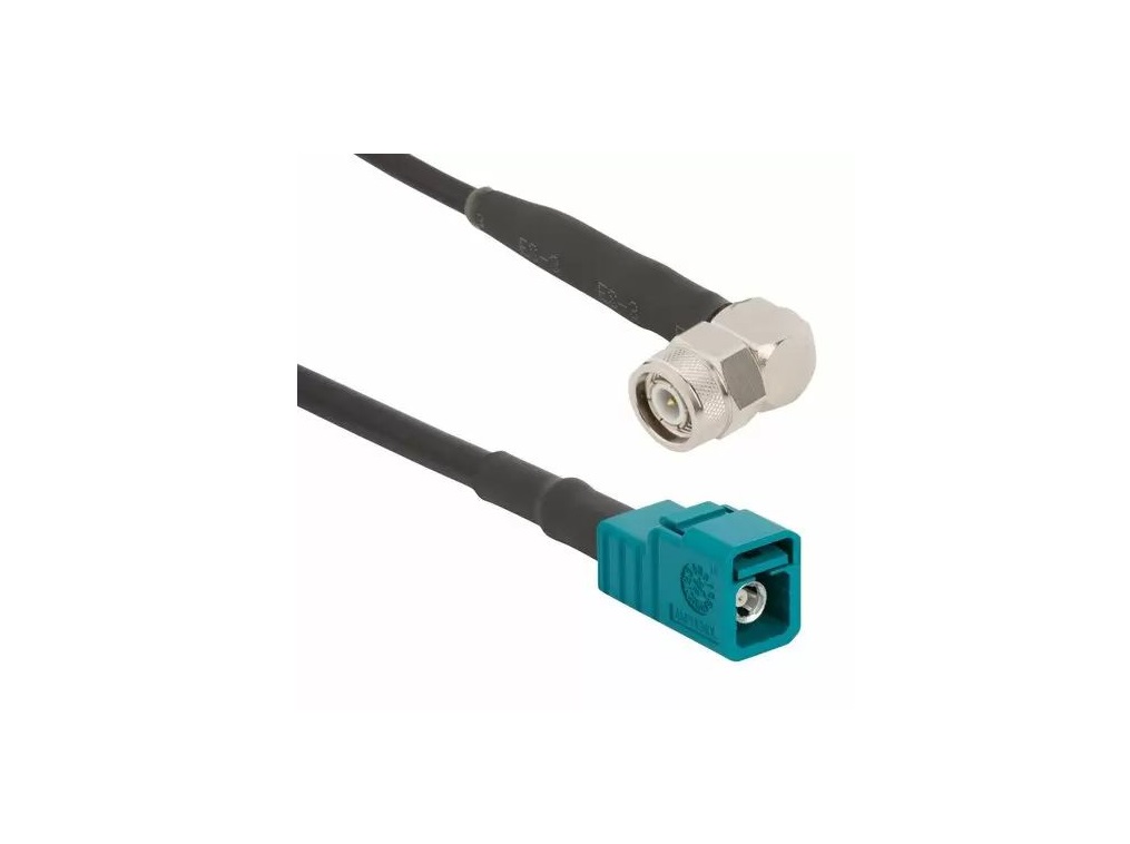
- Compatible with flexible, low‑loss and semi‑rigid/coaxial cables
- Precision-grade options ideal for phase‑sensitive microwave applications
Key Technical Details
- Impedance: 50 Ω
- Frequency Range: DC–18 GHz (connector/cable dependent; extended range to 34 GHz)
- Voltage Rating: 335 Vrms continuous; 1000 Vrms dielectric withstand
- Dielectric Material: PTFE
- Coupling Torque: 3–5 in·lbf (brass), 7–10 in·lbf (stainless steel)
Applications
- RF and microwave test and measurement systems
- Antenna feedlines and base station radios
- Aerospace and defense instrumentation
- Precision phase‑matching in radar and navigation systems
- OEM and lab RF interconnects requiring durability and accuracy
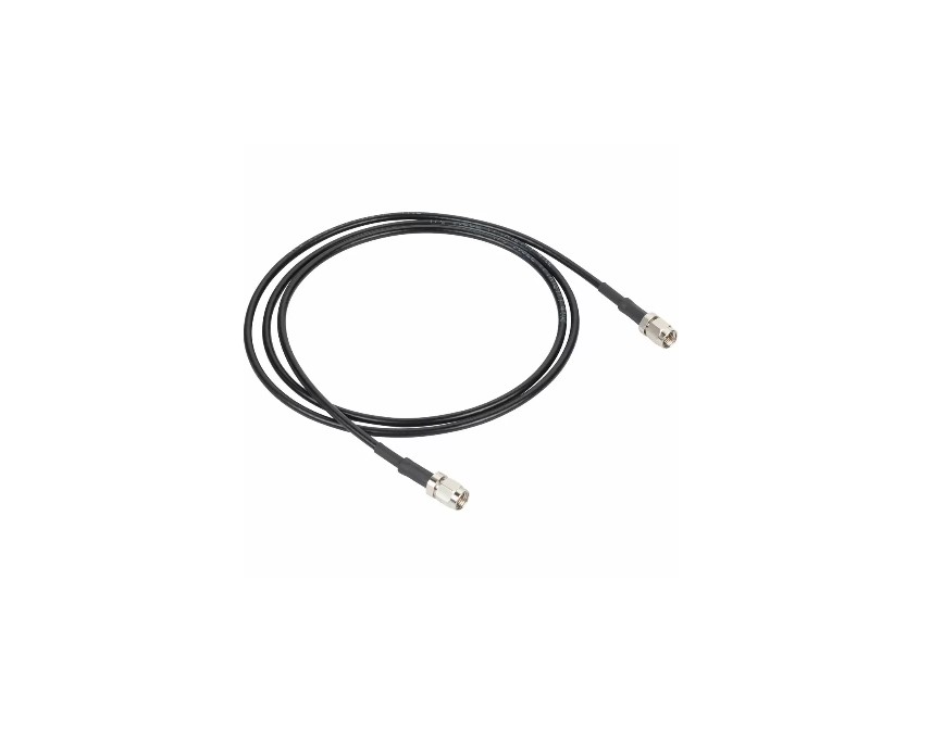
Browse our range of standard SMA cable assemblies or contact our engineers for custom rotary, phase-matched, or ultra-low-loss solutions.
Specifications
SMA Connectors
Electrical
| Impedance | 50 Ohm |
| Frequency Range | DC - 18 GHz (Up to 34 GHz on Extended Range Designs) |
| Voltage Rating | 335 Volts RMS Continuous |
| Dielectric Withstanding Voltage | 1000 VRMS Min |
| VSWR (Return Loss) | |
M39012 Straight Connectors |
|
.141" OD Copper Jacket Cable |
1.05 + .005 f (GHz) |
RG-58/RG-142 Group |
1.15 + .011 f (GHz) DC-12.4 GHz |
RG-174/RG-316 Group |
1.15 + .02 f (GHz) DC-12.4 GHz |
RG-178 Group |
1.20 + .025 f (GHz) DC-12.4 GHz |
M39012 Angle Connectors |
|
.141" OD Copper Jacket Cable |
1.10 + .01 f (GHz) |
RG-58/RG-142 Group |
1.15 + .02 f (GHz) DC-12.4 GHz |
RG-174/RG-316 Group |
1.15 + .03 f (GHz) DC-12.4 GHz |
RG-178 Group |
1.20 + .03 f (GHz) DC-12.4 GHz |
| Insulation Resistance | 5000 MΩ Min |
| Center Contact Resistance | 3.0 mΩ Max |
| Outer Contact Resistance | 2.0 mΩ Max |
| RF Leakage | -60 dB Max (DC - 3 GHz) |
| Insertion Loss | .06 √(f(GHz)) dB Max |
| Power Handling | 75 W @ 10 GHz @ 25ºC |
Environmental
| Temperature Range | |
Typical |
-65°C to +165°C |
Styrene Insulator or Phosphor Bronze Contact |
-40°C to +85°C |
| Thermal Shock | MIL-STD-202, Method 107 (Test Condition B) except high temp test @ +200°C |
| Corrosion | MIL-STD-202, Method 101 (Test Condition B) - 5% Salt Solution |
| Vibration | MIL-STD-202, Method 204 (Test Condition D) |
| Mechanical Shock | MIL-STD-202, Method 213 (Test Condition I) - No Discontinuity Permitted |
| Moisture Resistance | MIL-STD-202, Method 106 |
| Altitude | MIL-STD-202, Method 105 (Test Condition C) |
Mechanical
| Mating Cycles | 500 Min |
| Coupling Mechanism | Threaded |
| Interface Specification | MIL-STD-348 |
| Mating Torque (Stainless Steel Plug) | 0.8 - 1.1 N-m (7 - 10 in-lbs) |
| Mating Torque (Brass Plug) | 0.3 - 0.6 N-m (3 - 5 in-lbs) |
Note: These characteristics are typical and may not apply to all connectors.
Connector configurations may affect performance.
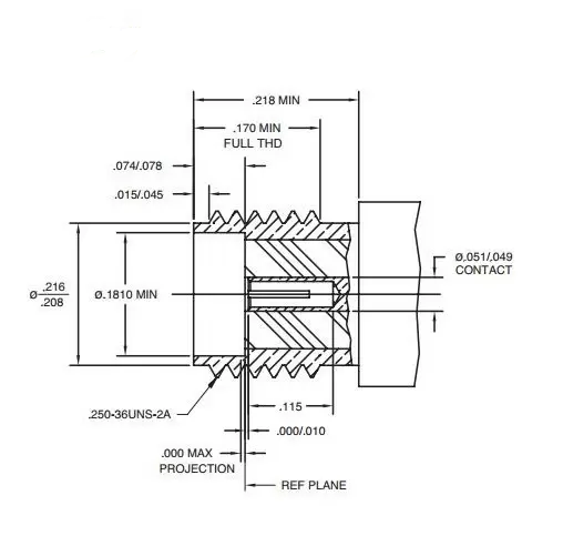
Interface Dimensions
Plug
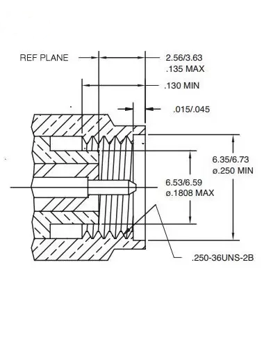
Jack
Related Resources

.png)
.jpg)
.png)
.png)


Send us a Message
Please fill in the form below and we will contact you very soon.
Fields marked with an asterisk (*) are required.