SMB Connectors
Overview
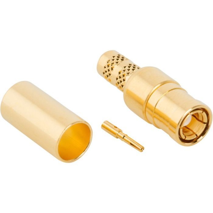
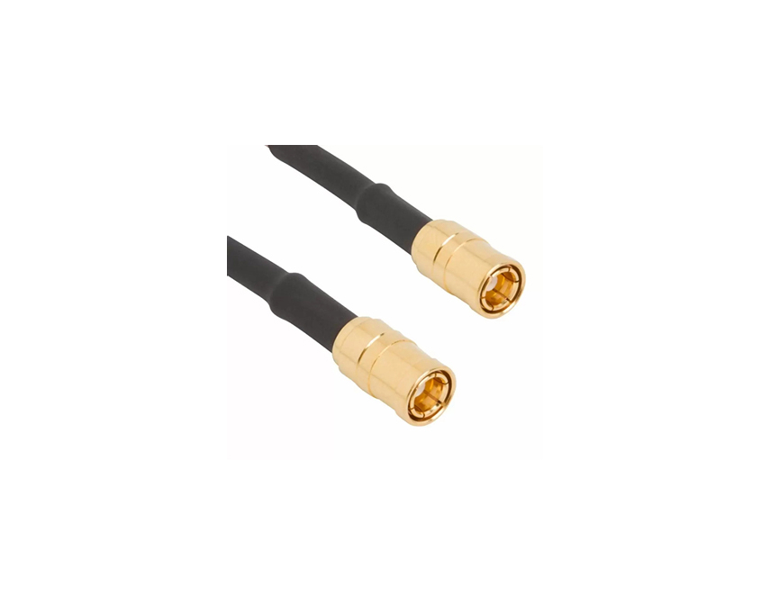
At Amphenol RF, our SMB connector series provides a proven and versatile solution for engineers and buyers seeking compact, quick-connect RF interfaces. The SMB family supports broadband performance, 50 Ω (and dedicated 75 Ω) impedance options and broad cable and PCB compatibility — making it a strong candidate for applications ranging from instrumentation to wireless infrastructure.
With its snap-on coupling mechanism, MIL-C-39012 interface compliance and MIL-STD-348 design lineage, the SMB series balances space-efficient packaging with reliable electrical performance.
Features and Benefits
- Snap-on coupling mechanism reduces installation time and allows for rapid mating/demating in field or assembly environments.
- Broadband capability: standard designs support DC to ~4 GHz, with extended-range variants rated to ~10 GHz.
- Available in both 50 Ω and 75 Ω impedance variants—supporting standard RF systems and video/broadcast applications.
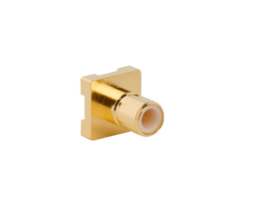
- Compact sub-miniature form-factor accommodates space-constrained board-to-cable or cable-to-board architectures.
- Variety of plating and material options (nickel, gold, tin-lead) satisfy cost, corrosion or solderability requirements.
- Low insertion-force PCB slide-on plug/jack variants enable dense board-to-board configurations with minimal mating strain.
Key Technical Details
- Impedance: 50 Ω standard; 75 Ω variants available for broadcast/video-centric systems.
- Frequency Range: DC to ~4 GHz in standard SMB designs; up to ~10 GHz in extended-range versions (dependent on connector configuration and cable).
- Mating Cycles: Minimum 500 mating cycles typical for SMB series.
- Temperature Range: −65 °C to +165 °C typical; performance may vary with configuration and cable type.
- Special Features: Snap-on coupling, 50 Ω/75 Ω options, multiple plating alternatives; note that standard SMB series from Amphenol RF are not hermetically sealed and IP-rated sealed variants are not listed for this series.
Applications
The SMB connector family is well suited for a wide range of system uses:
- Wireless infrastructure and base-station modules where compact, quick-connect RF interfaces are needed.
- Instrumentation and test equipment requiring frequent mate/demate operations and board-mount or cable-mount integration.
- Broadcast and video-link systems leveraging 75 Ω SMB variants for impedance-matched signal paths.
- GPS, telemetry and data-communications platforms needing space-efficient, high-density RF interconnect solutions.
- Cable-to-board or board-to-board interconnects in systems where mature supply chain, global availability and repeatable RF performance are requisite.
Explore our full SMB standard-product connector lineup. If you require a custom termination, alternate material, specialty plating or a tailored variant outside the standard offerings, please contact our engineering team for a bespoke solution.
Specifications
SMB Connectors
Electrical
| Impedance | 50 Ohm |
| Frequency Range | DC - 4 GHz (DC - 10 GHz on Extended Range Designs) |
| Voltage Rating | 335 Volts RMS Continuous |
| Dielectric Withstanding Voltage | 1000 VRMS Max |
| VSWR (Return Loss) |
|
|
RG-178/RG-196 Group
|
|
|
Straight Connectors
|
1.30 + .04 f (GHz) |
|
Right Angle Connectors
|
1.45 + .06 f (GHz) |
|
RG-174/RG-316/RG-188 Group
|
|
|
Straight Connectors
|
1.25 + .04 f (GHz) |
|
Right Angle Connectors
|
1.35 + .04 f (GHz) |
| Insulation Resistance | 1000 MΩ Min |
| Center Contact Resistance | 6 mΩ Max |
| Outer Contact Resistance | 1 mΩ Max |
| RF Leakage | -120 dB Max (DC - 3 GHz) |
| Insertion Loss |
|
|
Straight Connectors
|
.30 dB @ 1.5 GHz Max |
|
Right Angle Connectors
|
.60 dB @ 1.5 GHz Max |
| Power Handling | 95 W @ 1 GHz @ 25ºC |
Environmental
| Temperature Range | −65°C to +165°C |
| Thermal Shock | MIL-STD-202 Method 107 (Test Condition B) except high temp test @ +200°C |
| Corrosion | MIL-STD-202 Method 101 (Test Condition B) 5% Salt Solution |
| Vibration | MIL-STD-202 Method 204, snap on (Test Condition B) (15G's) |
| Mechanical Shock | MIL-STD-202 Method 213, snap on (Test Condition B) 75 G's @ 6 milliseconds 1/2 sine |
| Moisture Resistance | MIL-STD-202 Method 106 |
| Altitude | MIL-STD-202 Method 105 (Test Condition C) |
Mechanical
| Mating Cycles | 500 Min |
| Coupling Mechanism | Snap-On |
| Interface Specification | MIL-STD-348 |
| Engagement Force | 14 lbs (62 N) Max |
| Disengagement Force | 2 lbs (8.9 N) Max |
Note: These characteristics are typical and may not apply to all connectors.
Connector configurations may affect performance.
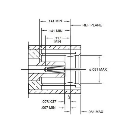
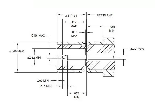
Interface Dimensions
Plug
Jack
Related Resources

Send us a Message
Please fill in the form below and we will contact you very soon.
Fields marked with an asterisk (*) are required.