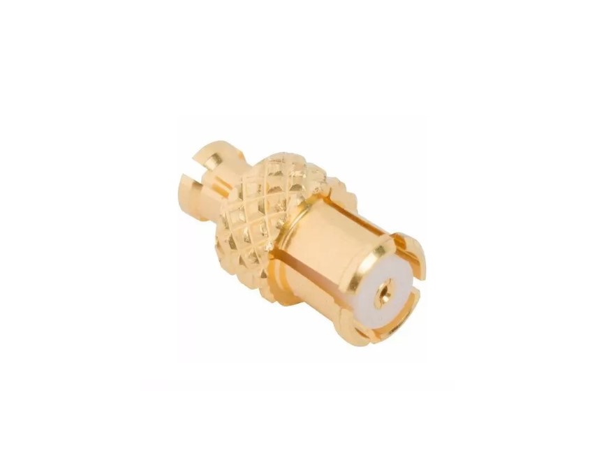
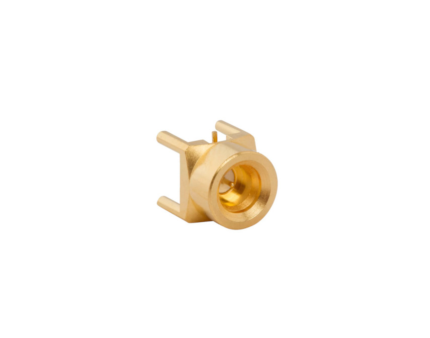
SMP Connectors
High-frequency, board-to-board blind-mate solutions in compact form
Overview
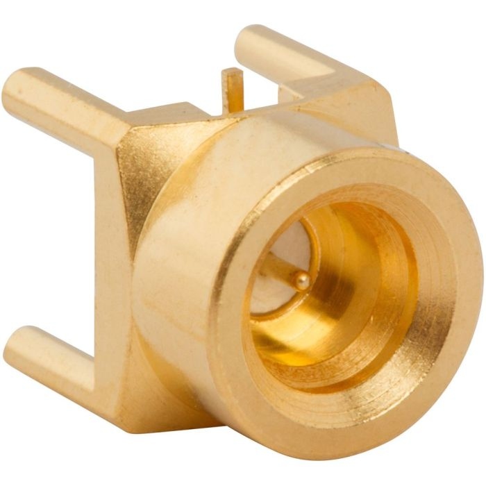
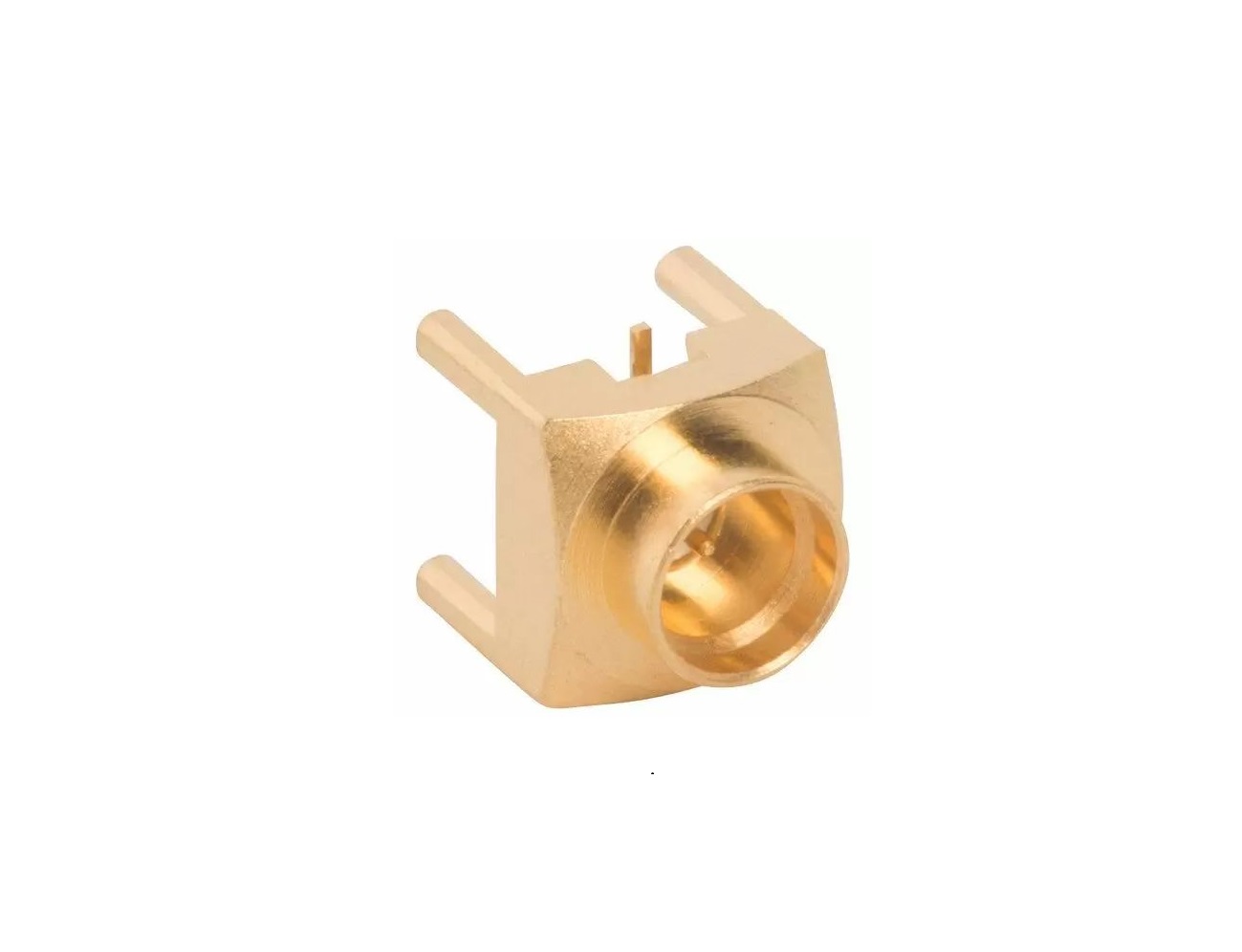
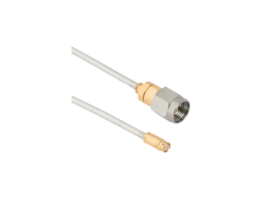
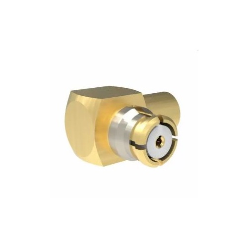
Amphenol RF’s SMP connectors deliver reliable RF performance in tight, board-to-board blind-mate environments. Their compact push‑on design enables fast, tool‑less assembly while preserving high-frequency integrity—all within a footprint optimized for dense PCB layouts.
Engineered for rugged applications, SMP connectors support broadband operation up to 40 GHz with precise impedance control. Ideal for modular systems, they simplify interconnect design without sacrificing RF performance or mechanical reliability.
Features and Benefits
- Broadband performance reaching up to 40 GHz
- Compact blind‑mate push‑on design for quick assembly
- High mechanical durability with excellent retention force
- Consistent 50 Ω contact system ensuring signal integrity
- Modular compatibility for multi-board system layouts
Key Technical Details
- Impedance: 50 Ω controlled
- RF frequency: Up to 40 GHz (dependent on cable/PCB layout)
- Blind‑mate coupling: Push‑on interface, no tools required
- Mechanical strength: High retention and contact force
- Surface finish: Gold-plated for enhanced conductivity
Applications
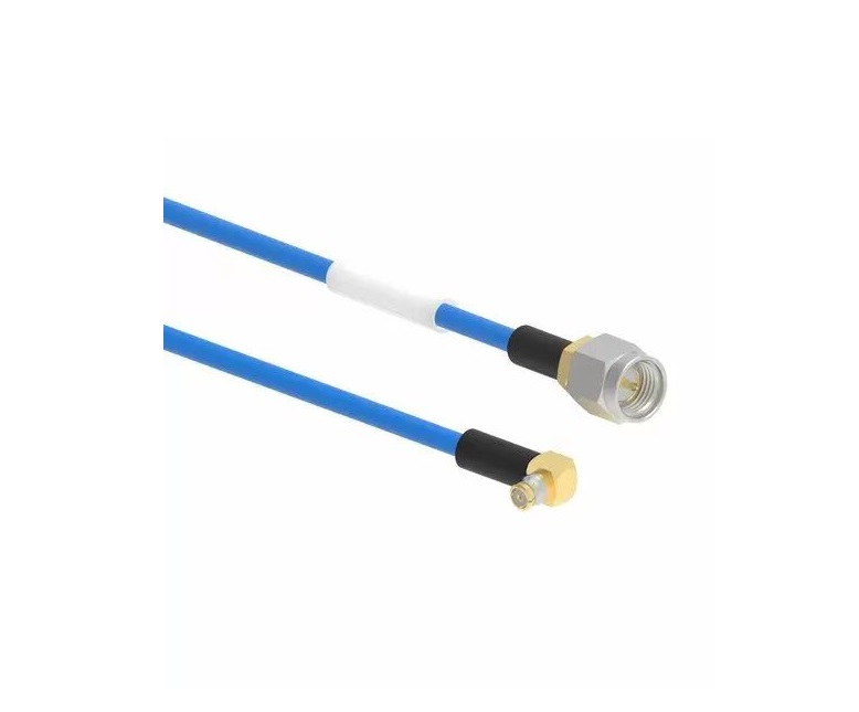
- Board‑to‑board wireless communication modules
- High‑speed test and measurement equipment
- Aerospace and defense RF subsystems
- Modular instrumentation arrays
- Ruggedized telecom hardware
Explore our catalog of SMP standard connectors. For custom centerline offsets, plating options or unique configurations, contact our expert team—we’re ready to help tailor a solution to your needs.
Specifications
SMP Connectors
Electrical
| Impedance | 50 Ohm |
| Frequency Range | DC - 26.5 GHz (DC - 40 GHz on Extended Range Designs) |
| Voltage Rating | 335 Volts RMS Max Continuous |
| Dielectric Withstanding Voltage | 500 VRMS Min |
| VSWR (Return Loss) |
|
|
DC - 18 GHz
|
1.2 (-21 dB) Max |
|
18 - 26.5 GHz
|
1.3 (-18 dB) Max |
|
26.5 - 40 GHz
|
1.7 (-12 dB) Max |
| Insulation Resistance | 5000 MΩ Min |
| Center Contact Resistance | 6 mΩ Max |
| Outer Contact Resistance | 2 mΩ Max |
| RF Leakage | -85 dB Max (DC - 4 GHz) |
| Insertion Loss | .1 √(f(GHz)) dB Max |
| Power Handling | 32 W @ 1 GHz @ 25ºC |
Environmental
| Temperature Range | −65°C to +165°C |
| Thermal Shock | MIL-STD-202, Method 107, Condition C |
| Corrosion | MIL-STD-202 Method 101 (Test Condition B) - 5% Salt Solution |
| Vibration | MIL-STD-202, Method 204, Condition B |
| Mechanical Shock | MIL-STD-202, Method 213, Condition B |
| Moisture Resistance | MIL-STD-202, Method 106, Condition D |
Mechanical
| Mating Cycles | 100 Min |
| Coupling Mechanism | Push-On |
| Interface Specification | MIL-STD-348 |
| Engagement Force | ≤ 15.0 lbs (40 N) |
| Disengagement Force | ≤ 0.5 lbs (2N) |
| Mechanical Misalignment |
|
|
Axial
|
0.25 mm |
|
Radial
|
0.51 mm |
|
Min Board to Board Distance
|
9.1 mm |
Note: These characteristics are typical and may not apply to all connectors.
Connector configurations may affect performance.
Related Resources

.png)


Send us a Message
Please fill in the form below and we will contact you very soon.
Fields marked with an asterisk (*) are required.