SMPM Connectors
Micro‑miniature blind‑mate RF connectors for ultra‑high frequency board‑to‑board and cable applications
Overview
Amphenol RF’s SMPM connectors are purpose-built for space‑constrained, high‑frequency environments. With a compact yet robust design supporting DC–65 GHz performance, these connectors fit seamlessly into miniaturized modules, test setups and blind‑mate scenarios like board‑to‑board and cable‑to‑board systems.
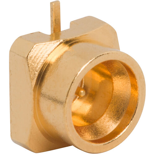
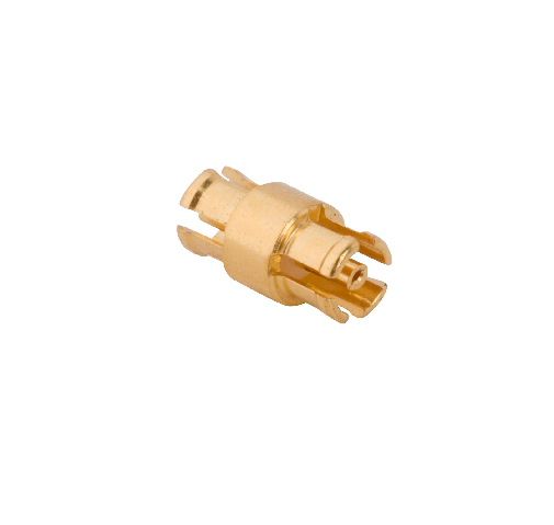
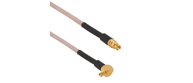
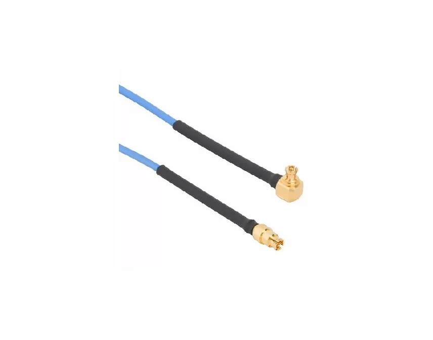
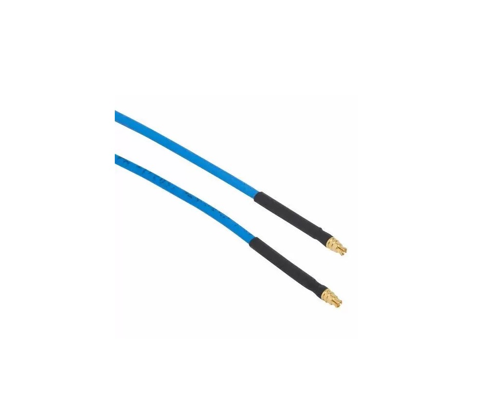
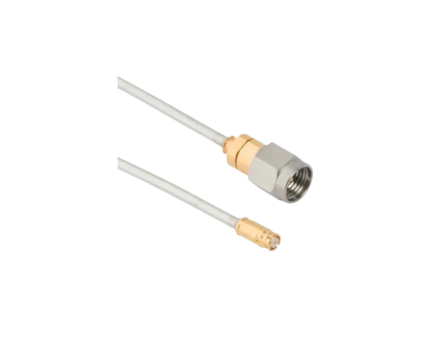
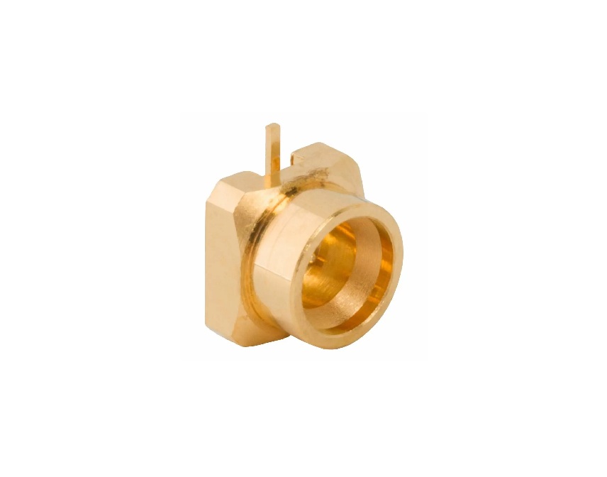
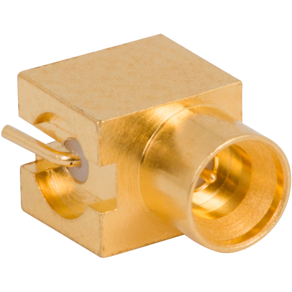
Available in both push‑on smooth‑bore and snap‑on full‑detent styles, SMPM connectors ensure reliable mating, even under slight misalignment. Choose from straight or right‑angle cable plugs and a range of PCB receptacles—surface‑mount, through‑hole, or edge‑launch—for versatile system integration.
Features and Benefits
- Ultra-high frequency range: Supports DC–65 GHz for cutting-edge RF and microwave systems
- Compact micro‑miniature footprint: Ideal for tight enclosure and high‑density board layouts
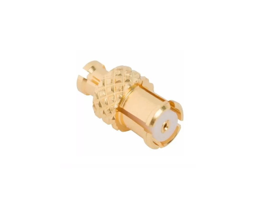
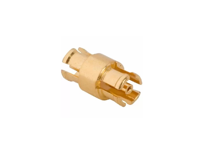
- Blind‑mate capability: Optional bullet adapters enable tolerance for axial/radial misalignment
- Two mating styles: Smooth‑bore (quick push-on) and full‑detent (secure engagement)
- Versatile terminations: Cable‑to‑board, board‑to‑board and cable assemblies with semi‑rigid or flexible coax
Key Technical Details
- Impedance: 50 Ω
- Frequency range: DC to 65 GHz (connector & cable/PCB trace dependent)
- Dielectric withstanding voltage: ≥ 325 Vrms
- PCB spacing: down to ~8.65 mm (with bullet adapter)
- Misalignment compensation: ~0.51 mm radial, ~0.25 mm axial float
Applications
- High-density board-to-board RF interconnects
- Microwave test instrumentation
- Antenna front-end modules
- Handheld radios, UAVs and portable systems
- Quantum computing and medical diagnostics equipment
Explore our range of SMPM standard connectors for high-performance, space-efficient RF solutions. If your design requires custom spacing, orientation or mating force, our engineering team is ready to help craft a tailored SMPM interconnect solution.
Specifications
SMPM Connectors
Electrical
| Impedance | 50 Ohm |
| Frequency Range | DC - 26.5 GHz (DC - 65 GHz on Extended Range Designs) |
| Dielectric Withstanding Voltage | 325 VRMS Min |
| VSWR (Return Loss) |
|
|
DC - 10 GHz
|
1.15 (-23 dB) Max |
|
10 - 26.5 GHz
|
1.25 (-19 dB) Max |
|
26.5 - 50 GHz
|
1.35 (-16 dB) Max |
| Insulation Resistance | 5000 MΩ Min |
| Center Contact Resistance | 6 mΩ Max |
| Outer Contact Resistance | 2 mΩ Max |
| RF Leakage | -85 dB Max (DC - 4 GHz) |
| Insertion Loss | .1 √(f(GHz)) dB Max |
| Power Handling | 16 W @ 1 GHz @ 25ºC |
Environmental
| Temperature Range | −65°C to +165°C |
| Thermal Shock | MIL-STD-202, Method 107, Condition B |
| Corrosion | MIL-STD-202 Method 101 (Test Condition B) - 5% Salt Solution |
| Vibration | MIL-STD-202, Method 204, Condition B |
| Mechanical Shock | MIL-STD-202, Method 213, Condition A |
| Moisture Resistance | MIL-STD-202, Method 106 |
Mechanical
| Mating Cycles | 100 Min (Full Detent), 500 Min (Smooth Bore) |
| Coupling Mechanism | Push-On |
| Interface Specification | MIL-STD-348 |
| Engagement Force | ≤ 15N |
| Disengagement Force | ≤ 2N |
| Mechanical Misalignment |
|
|
Axial
|
0.25 mm |
|
Radial
|
3° |
|
Min Board to Board Distance
|
6.6 mm |
Note: These characteristics are typical and may not apply to all connectors.
Connector configurations may affect performance.
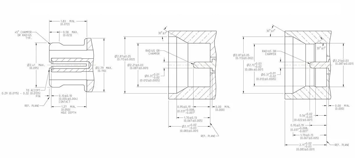
Interface Dimensions
Plug (Bullet)
Jack (Smooth Bore)
Jack (Full Detent)
Related Resources


Send us a Message
Please fill in the form below and we will contact you very soon.
Fields marked with an asterisk (*) are required.