SMZ Connectors
High‑density, 75 Ω RF coaxial interface optimized for instrumentation and broadcast systems
Overview
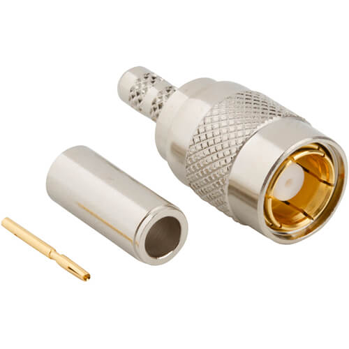
Amphenol RF’s SMZ connectors deliver industry-standard performance in a compact, rugged design tailored for dense rack‑mount equipment and test environments. With 75 Ω impedance and threaded coupling, they balance reliability with space efficiency. Our lineup includes right-angle and straight cable-mount plugs, panel-mount jacks and adapters engineered for broadcast wavelengths.
Engineered for DC–3 GHz operation, SMZ connectors offer precision interconnects for audio/video distribution, data acquisition systems and satellite IF pathways. The robust shell and PTFE dielectric support consistent insertion loss and impedance matching even in high-cycle use. Ideal for custom cable assemblies, they are backed by Amphenol RF’s full range of datasheets and distributor-verified specs.
Features and Benefits
- Compact 75 Ω interface for high-density rack or panel installations
- Threaded coupling ensures secure mate with good shielding
- Broad cable compatibility, including low-loss broadcast and RG‑59 types
- Panel and cable-mount options simplify system integration
- Durable design, rated for frequent mating, ideal for A/V testing setups
Key Technical Details
- Characteristic impedance: 75 Ω
- Threaded coupling mechanism for reliable connection
- Right-angle and straight cable-mount, panel-mount jacks available
Applications
- Broadcast and 12G‑capable video signal paths
- RF distribution in test and measurement equipment
- Satellite IF cabling and terrestrial microwave links
- Instrumentation panels and data acquisition systems
Explore our SMZ product portfolio or contact us for custom assemblies tailored to your broadcast or instrumentation needs.
Our engineering team can assist with cable type, adapter or configuration customizations to fit your application.
Specifications
SMZ Connectors
Electrical
| Impedance | 75 Ohm |
| Frequency Range | DC - 2 GHz |
| Voltage Rating | 335 Volts RMS Continuous |
| Dielectric Withstanding Voltage | 1000 VRMS Max |
| Insulation Resistance | 1000 MΩ Min |
| Center Contact Resistance | 6 mΩ Max |
| Outer Contact Resistance | 1 mΩ Max |
| RF Leakage | -55 dB Max (2 - 3 GHz) |
| Insertion Loss |
|
|
Straight Connectors
|
.03 dB Max @ 1.5 GHz |
|
Right Angle Connectors
|
.06 dB Max @ 1.5 GHz |
Environmental
| Temperature Range | −65°C to +165°C |
| Thermal Shock | MIL-STD-202, Method 107 (Test Condition B) except high temp test @ +200°C |
| Corrosion | MIL-STD-202, Method 101 (Test Condition B) 5% salt solution |
| Vibration | MIL-STD-202, Method 204, Snap On (Test Condition B) (15G's) |
| Mechanical Shock | MIL-STD-202, Method 213, Snap on (Test Condition B) 75 G's @ 6 milliseconds 1/2 sine |
| Moisture Resistance | MIL-STD-202, Method 106 |
| Altitude | MIL-STD-202, Method 105 (Test Condition C) |
Mechanical
| Mating Cycles | 500 Min |
| Coupling Mechanism | Snap-On |
| Engagement Force | 14 lbs (62 N) Max |
| Disengagement Force | 2 lbs (8.9 N) Min |
Note: These characteristics are typical and may not apply to all connectors.
Connector configurations may affect performance.
Send us a Message
Please fill in the form below and we will contact you very soon.
Fields marked with an asterisk (*) are required.