SSMC Connectors
Compact high-frequency solutions engineered for board-to-board and coaxial cable applications in space-constrained designs
Overview
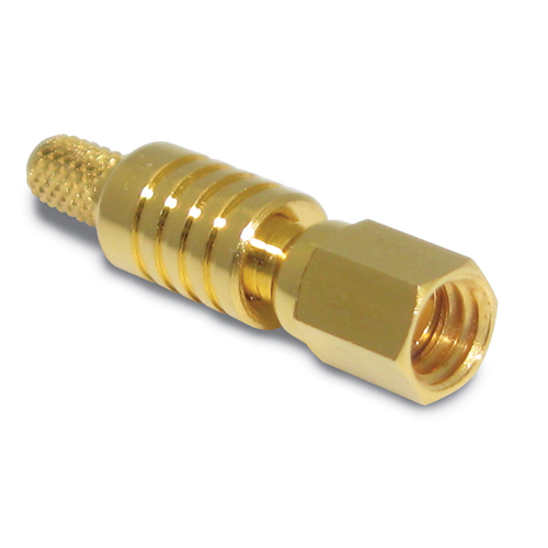
Amphenol RF’s SSMC connectors offer a reliable and compact interface ideal for high-frequency applications where space and performance are critical. These subminiature connectors provide secure mechanical mating with threaded coupling and support stable electrical performance up to 12.4 GHz, depending on the cable configuration.
The SSMC series includes both cable and PCB-mounted options, offering flexible solutions for RF interconnect systems. With a focus on performance and ease of integration, these connectors are well-suited for precision systems requiring miniature solutions with threaded retention.
Features and Benefits
- Compact subminiature design ideal for dense packaging
- Threaded coupling mechanism ensures secure connection
- Available in both cable and board mount configurations
- Compatible with a wide range of flexible cables
- Gold-plated contacts for improved conductivity and corrosion resistance
Key Technical Details
- Standard 50 ohm impedance for RF signal integrity
- Performance up to 12.4 GHz, supporting high-frequency signal transmission
- Available in plug and jack versions for system flexibility
- PCB and panel mount designs available for versatile integration
Applications
- Military and aerospace systems
- RF instrumentation and test equipment
- Wireless base stations and infrastructure
- Board-to-board interconnect in compact systems
Browse our standard SSMC connector solutions or contact us for a custom configuration to meet your specific design needs.
Specifications
SSMC Connectors
Electrical
| Impedance | 50 Ohm |
| Frequency Range | DC - 12.4 GHz |
| Voltage Rating | 250 Volts RMS Continuous |
| Dielectric Withstanding Voltage | 750 VRMS Min |
| VSWR (Return Loss) |
|
|
DC - 6 GHz
|
1.2 +0.02*f (GHz) Max |
| Insulation Resistance | 1000 MΩ Min |
| Center Contact Resistance | 5.0 mΩ Max |
| Outer Contact Resistance | 2.5 mΩ Max |
| RF Leakage | -50 dB Max (2 - 3 GHz) |
| Insertion Loss | .1 √(f(GHz)) dB Max |
Environmental
| Temperature Range | −65°C to +165°C |
| Thermal Shock | MIL-STD-202, Method 107 (Test Condition B) except high temp test @ +200°C |
| Corrosion | MIL-STD-202, Method 101 (Test Condition B) - 5% Salt Solution |
| Vibration | MIL-STD-202, Method 204 (Test Condition D) |
| Mechanical Shock | MIL-STD-202, Method 213 (Test Condition B) - No Discontinuity Permitted |
| Moisture Resistance | MIL-STD-202, Method 106 |
Mechanical
| Mating Cycles | 500 Min |
| Coupling Mechanism | Threaded |
| Interface Specification | IEC-169-20 |
| Mating Torque | 0.2 N-m (28-32 in-oz) |
Note: These characteristics are typical and may not apply to all connectors.
Connector configurations may affect performance.
Send us a Message
Please fill in the form below and we will contact you very soon.
Fields marked with an asterisk (*) are required.