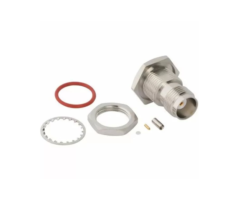
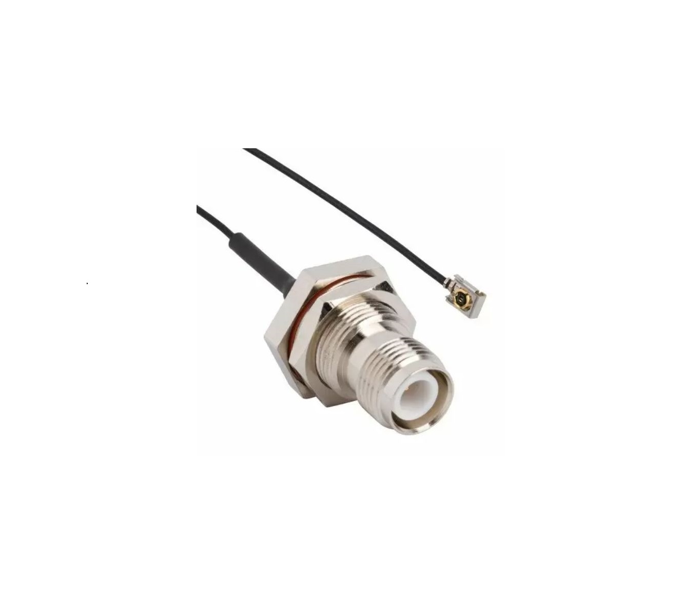
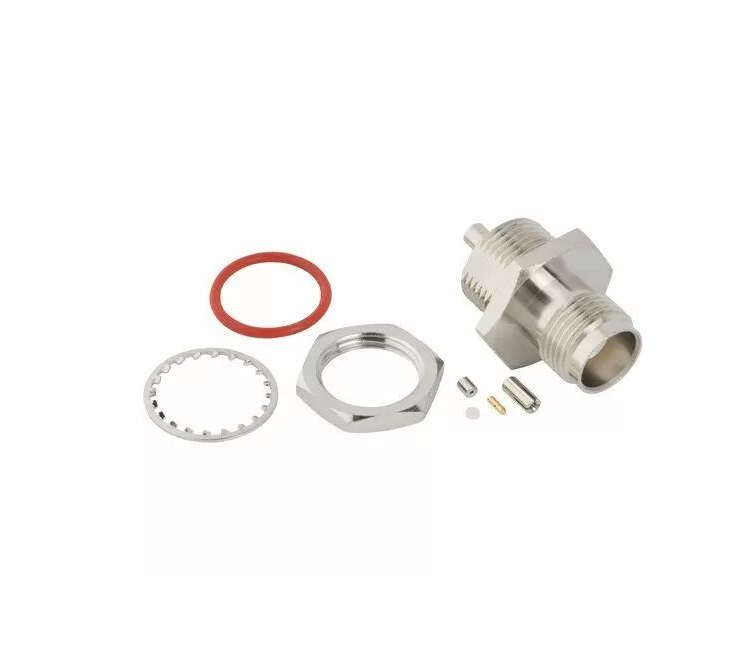
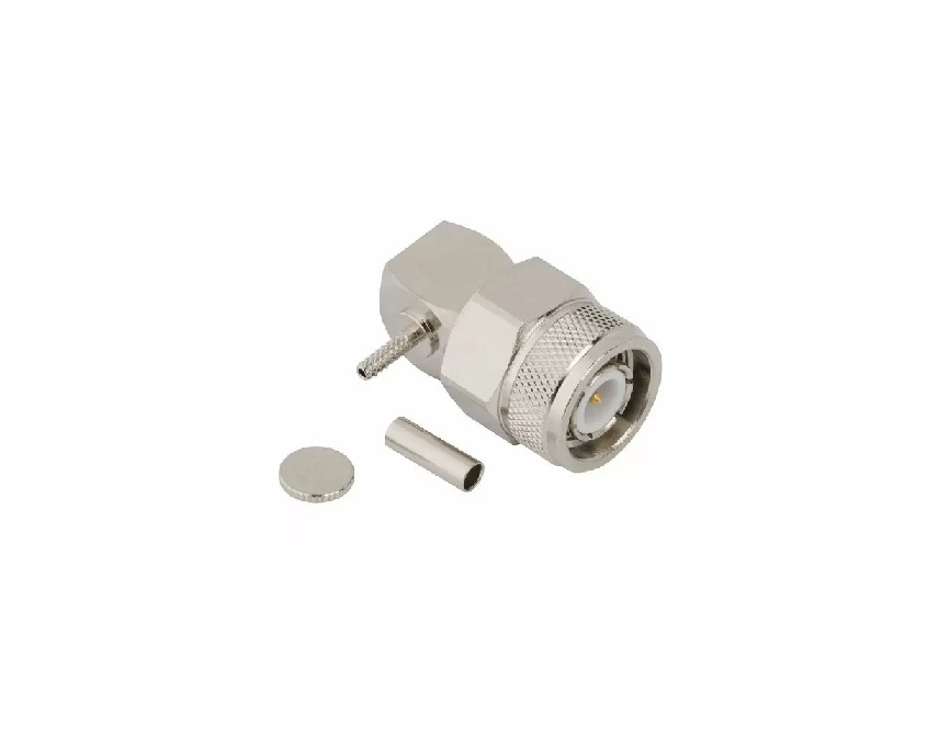
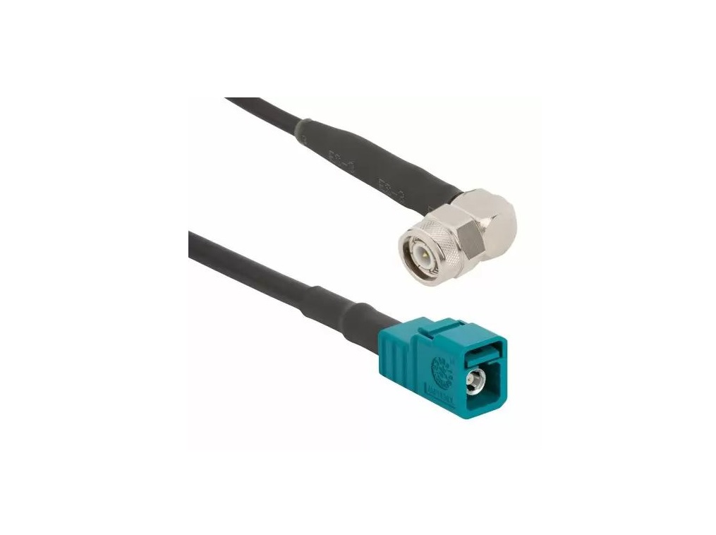
TNC Connectors
Reliable threaded RF solutions for secure and high-frequency performance in demanding environments
Overview
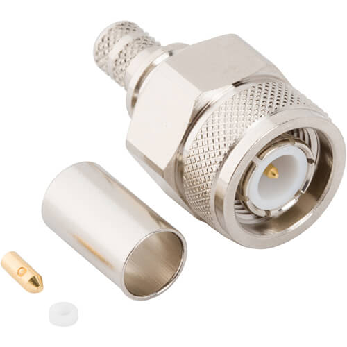
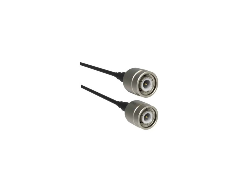
TNC connectors from Amphenol RF are a durable and high-performance solution for RF applications requiring a secure threaded interface. These connectors are ideal for use in environments where vibration and mechanical stress are a concern and are designed to provide consistent electrical performance across a range of frequencies.
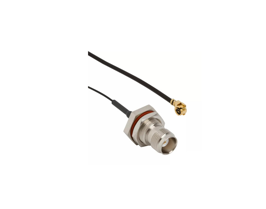
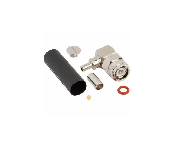
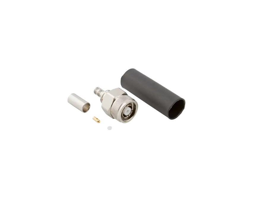
The threaded coupling mechanism ensures a stable and reliable connection, making TNC connectors a popular choice for test and measurement systems, communication infrastructure and industrial RF installations. Available in a wide array of configurations, including straight and right-angle options, TNC connectors are engineered for versatility and ease of integration into existing systems.
Features and Benefits
- Threaded coupling mechanism for vibration resistance
- High-frequency performance up to 11 GHz (cable dependent)
- Available in 50 ohm and 75 ohm versions
- Broad range of standard and custom configurations
- Gold- and silver-plated contact options for optimized conductivity
Key Technical Details
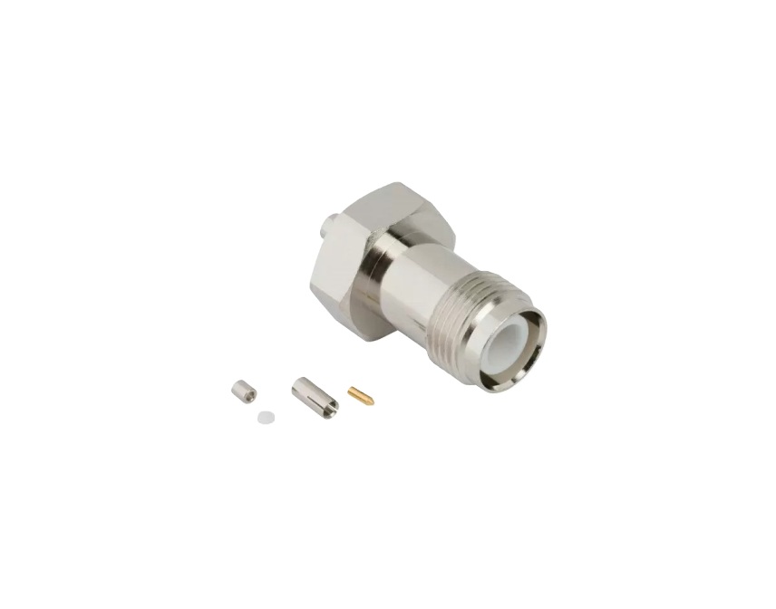
- Supports both standard and reverse polarity formats
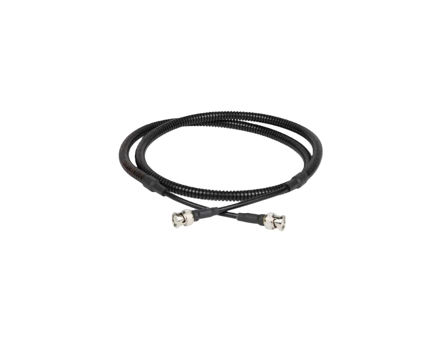
- Commonly used with RG-58, RG-142, RG-316 and similar coax cables
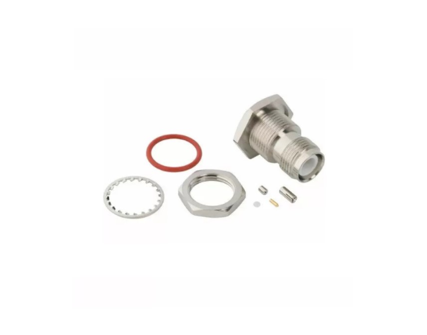
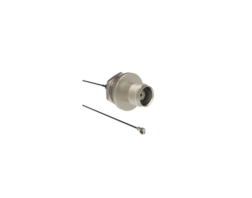
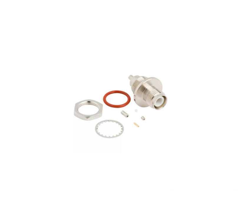
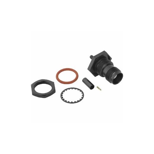
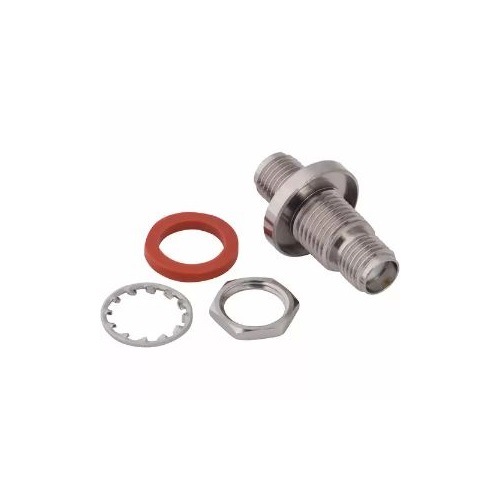
- Compatible with a variety of mounting styles, including bulkhead and panel mount
- Options available for both crimp and clamp cable terminations
- IP67 sealed versions available for outdoor and harsh environments
Applications
- Wireless infrastructure and cellular base stations
- Test and measurement equipment
- Antenna connections for Wi-Fi and IoT systems
- Industrial automation and control systems
- Broadband and broadcast systems
Browse our full selection of standard TNC connectors or contact us to discuss a custom RF solution tailored to your application.
Specifications
TNC Connectors
Electrical
| Impedance | 50 Ohm |
| Frequency Range | DC - 11 GHz (DC - 18 GHz on Extended Range Designs) |
| Voltage Rating | 500 Volts Peak |
| Dielectric Withstanding Voltage | 1500 VRMS Max |
| VSWR (Return Loss) |
|
|
DC - 11 GHz
|
1.3 (-18 dB) Max |
| Insulation Resistance | 5000 MΩ Min |
| Center Contact Resistance | 1.5 mΩ Max |
| Outer Contact Resistance | 0.2 mΩ Max |
| RF Leakage | -60 dB Max @ 3 GHz |
| Insertion Loss |
|
|
M39012 Straight Connectors
|
0.18 dB Max @ 9 GHz |
|
M39012 Right Angle Connectors
|
0.21 dB Max @ 9 GHz |
| Power Handling | 316 W @ 1 GHz @ 25ºC |
Environmental
| Temperature Range | −65°C to +165°C |
| Thermal Shock | MIL-STD-202, Method 107 (Test Condition B) except high temp test @ +200°C |
| Corrosion | MIL-STD-202, Method 101 (Test Condition B) - 5% Salt Solution |
| Vibration | MIL-STD-202, Method 204 (Test Condition B) |
| Mechanical Shock | MIL-STD-202, Method 213 (Test Condition G) - No Discontinuity Permitted |
| Moisture Resistance | MIL-STD-202, Method 106 |
| Altitude | MIL-STD-202 Method 105 (Test Condition C) |
Mechanical
| Mating Cycles | 500 Min |
| Coupling Mechanism | Threaded |
| Interface Specification | MIL-STD-348 |
| Mating Torque | 4 - 6 inch-pounds (0.51 - 0.67 N-m) |
Note: These characteristics are typical and may not apply to all connectors.
Connector configurations may affect performance.
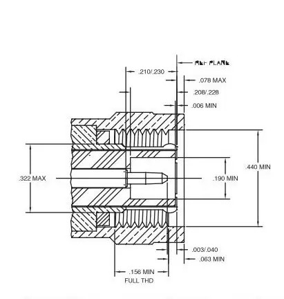
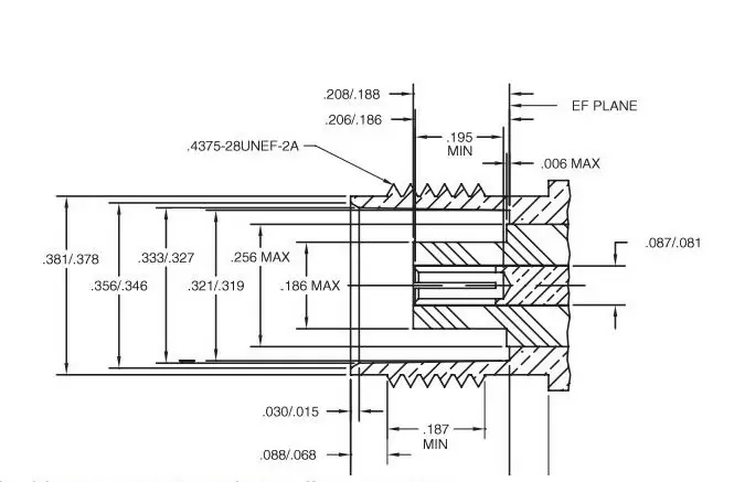
Interface Dimensions
Plug
Jack
Related Resources

.png)


")

Send us a Message
Please fill in the form below and we will contact you very soon.
Fields marked with an asterisk (*) are required.