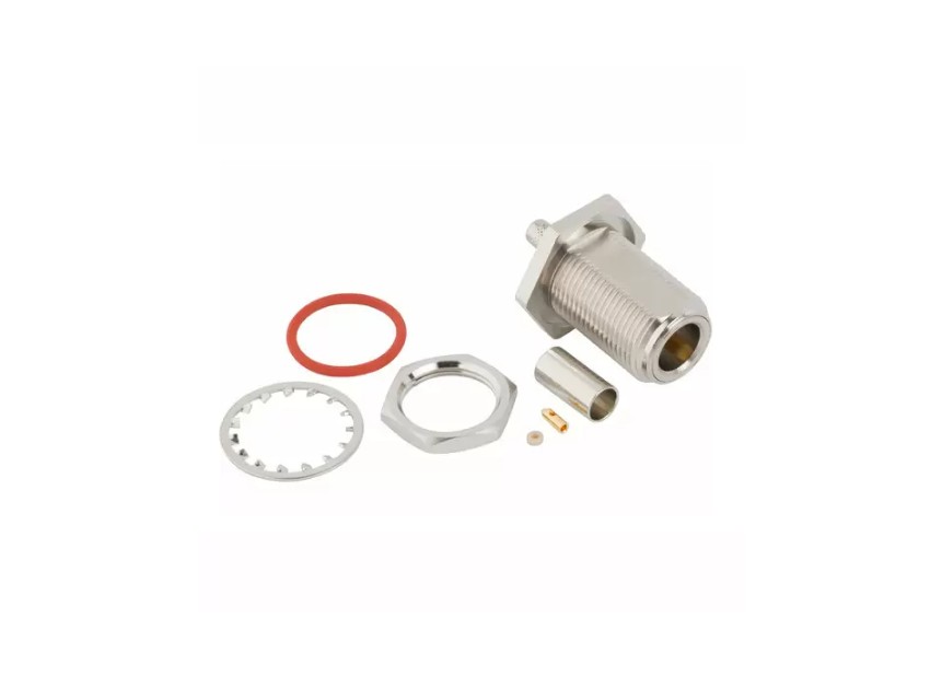
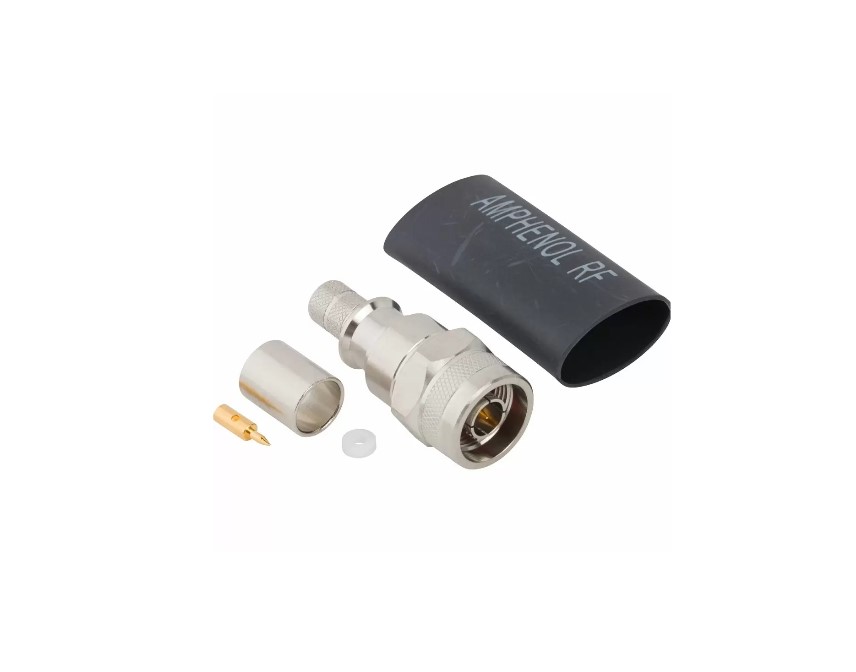
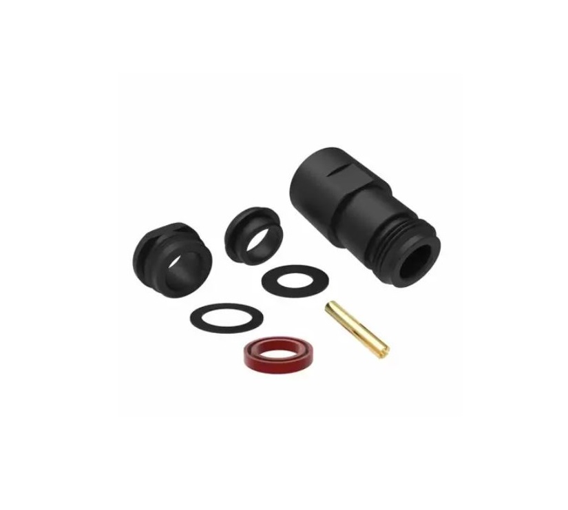
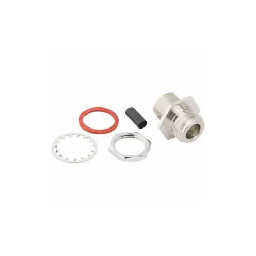
RP-N-Type Connectors
Premium reverse-polarity N‑type connectors delivering secure, high-performance RF for advanced systems
Overview
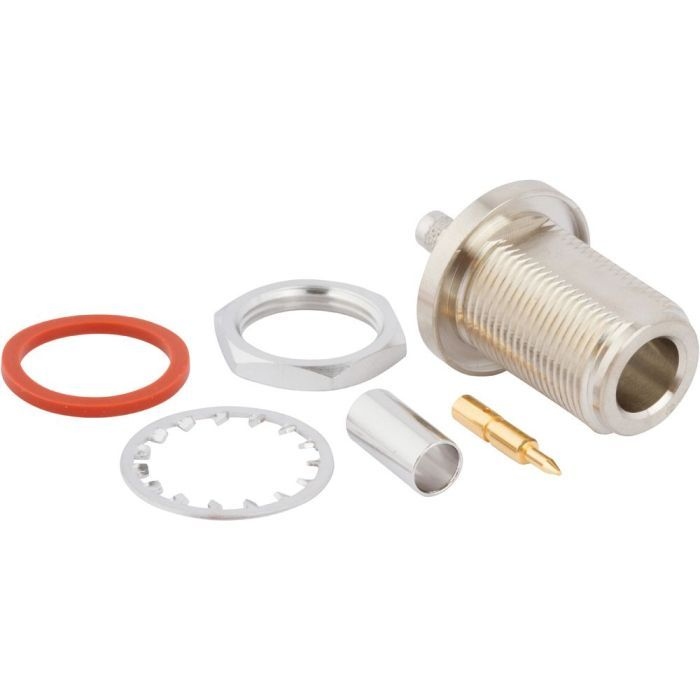
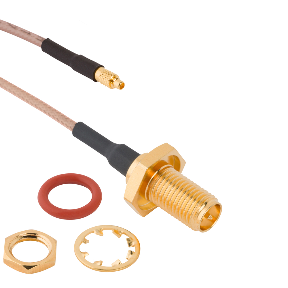
Amphenol RF’s RP‑N‑Type connectors are designed to meet demands for reverse-polarity standardization in Wi‑Fi, cellular and IoT applications, while preserving the mechanical and electrical integrity of traditional Type‑N. These connectors provide dependable 50 ohm performance in a durable interface that prevents unintended mating with conventional N‑type parts.
Engineered for reliable connections across a broad frequency spectrum, RP‑N‑Type connectors offer high power handling and environmental robustness. They're ideal for OEM, telecom and wireless developers requiring secure RP‑N data links with consistent phase and amplitude characteristics.
Features and Benefits
- Reverse-polarity interfaces comply with regulatory standards while minimizing cross-connect risk
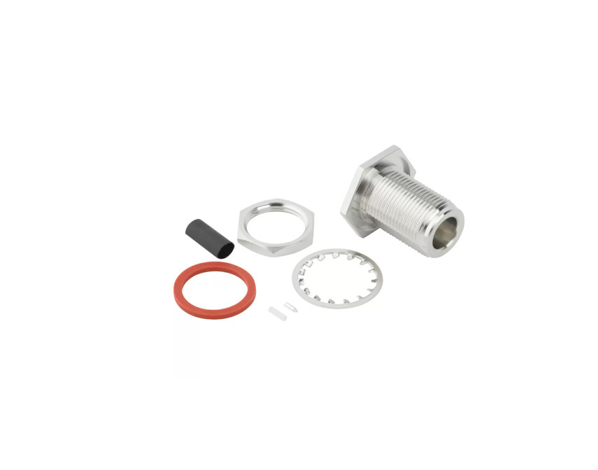
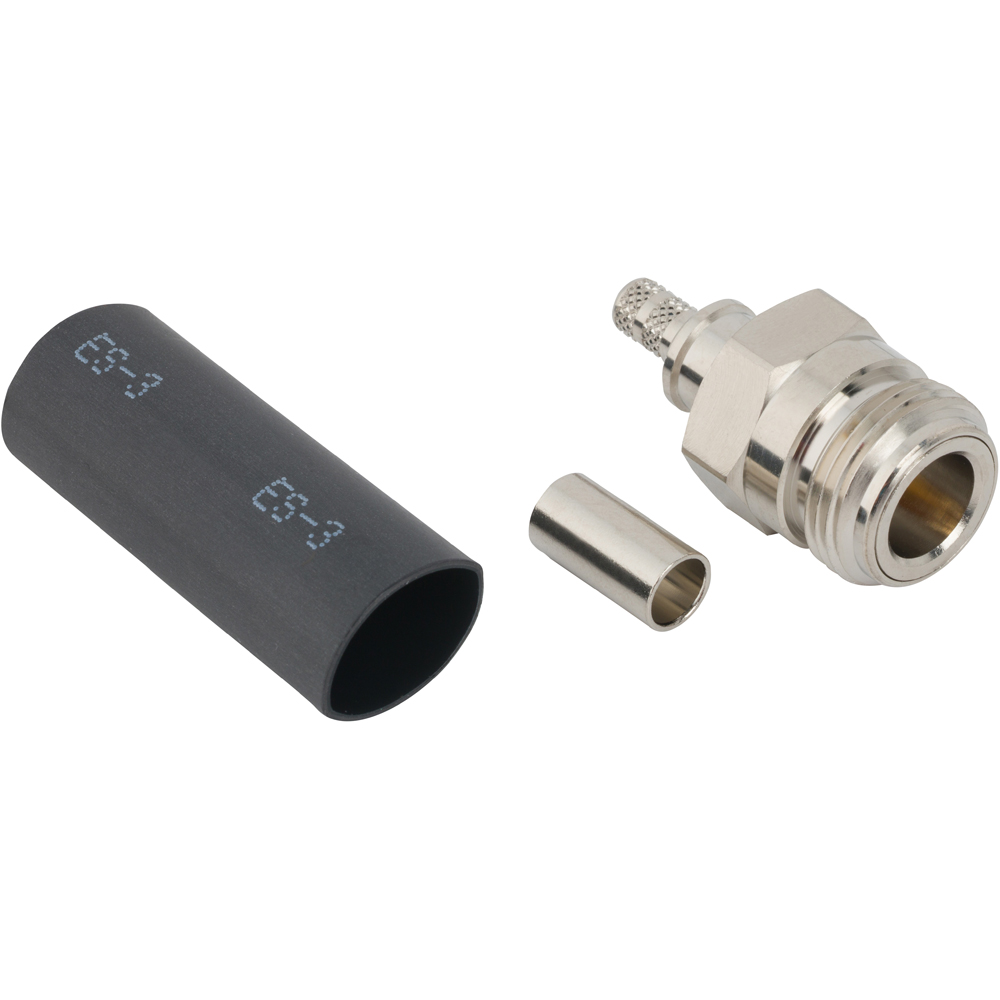
- Rugged Type‑N body ensures waterproof, threaded sealing and superior mechanical endurance
- DC–11 GHz performance, suitable for most Wi‑Fi, LTE and general RF workloads
- High power handling supports applications with elevated RF power demands
- Wide temperature range adapts to both indoor and field-deployed equipment
Key Technical Details
- Impedance: 50 Ω
- Frequency Range: DC–11 GHz (connector + cable dependent)
- Voltage Handling: ~500 Vrms continuous
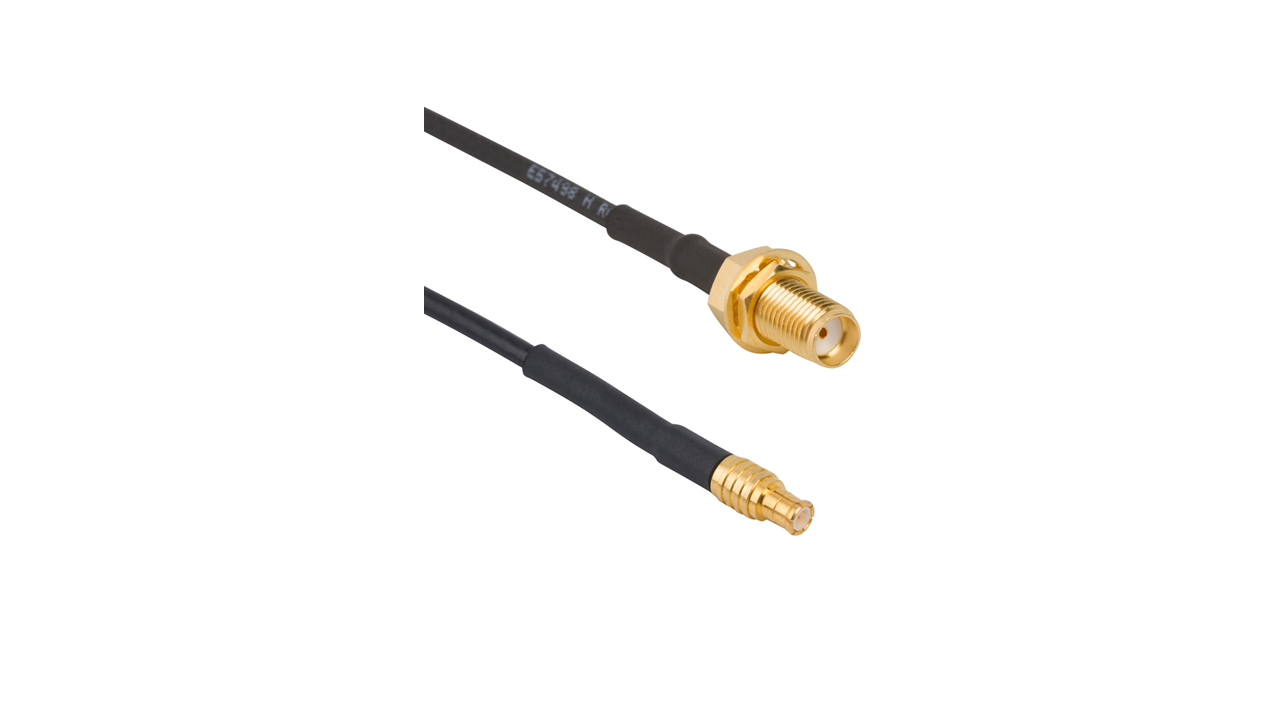
- Coupling: Threaded 5/8-24 coupling compatible with Type‑N form factor
Applications
- Wi-Fi and cellular external antennas
- Fixed wireless and IoT devices
- Test and measurement systems
- Public safety and surveillance RF installations
Browse our standard RP‑N‑Type connectors for ready-to-deploy RF interconnects. If you need custom configurations, corrosion-resistant plating or unique cable assemblies, contact us today for expert customization support.
Specifications
N-Type Connectors
Electrical
| Impedance | 50 Ohm |
| Frequency Range | DC - 11 GHz (DC - 18 GHz on Extended Range Designs) |
| Voltage Rating | 500 Volts RMS Continuous |
| Dielectric Withstanding Voltage | 1500 VRMS Max |
| VSWR (Return Loss) | |
|
M39012 Straight Connectors
|
|
|
DC - 11 GHz
|
1.30 (-18 dB) Max |
|
M39012 Right Angle Connectors
|
|
|
DC - 9 GHz
|
1.35 (-16 dB) Max |
|
9 - 11 GHz
|
1.5 (-14 dB) Max |
| Insulation Resistance | 5000 MΩ Min |
| Center Contact Resistance | 1 mΩ Max |
| Outer Contact Resistance | .4 mΩ Max |
| RF Leakage | -90 dB Max (DC - 3 GHz) |
| Insertion Loss | |
|
M39012 Straight Connectors
|
0.15 dB Max (DC - 9 GHz) |
|
M39012 Right Angle Connectors
|
0.30 dB Max (DC - 10 GHz) |
| Passive Intermodulation (PIM) | -166 dBc with 2 X 43 dBm inputs |
| Power Handling | 300 W @ 10 GHz @ 25ºC |
Environmental
| Temperature Range | |
|
Typical
|
−65°C to +165°C |
|
Styrene Insulator or Phosphor Bronze Contact
|
−40°C to +85°C |
| Thermal Shock | MIL-STD-202, Method 107 (Test Condition B) except high temp rest @ +200°C |
| Corrosion | MIL-STD-202, Method 101 (Test Condition B) - 5% Salt Solution |
| Vibration | MIL-STD-202, Method 204 (Test Condition B) |
| Mechanical Shock | MIL-STD-202, Method 213 (Test Condition I) - No Discontinuity Permitted |
| Moisture Resistance | MIL-STD-202, Method 106 |
| Altitude | MIL-STD-202 Method 105 (Test Condition C) |
Mechanical
| Mating Cycles | 500 Min |
| Coupling Mechanism | Threaded |
| Interface Specification | MIL-STD-348 |
| Coupling Mechanism Retention Force | 100 lbs Min |
| Mating Torque, Min Working | 8-12 inch-pounds |
Note: These characteristics are typical and may not apply to all connectors.
Connector configurations may affect performance.
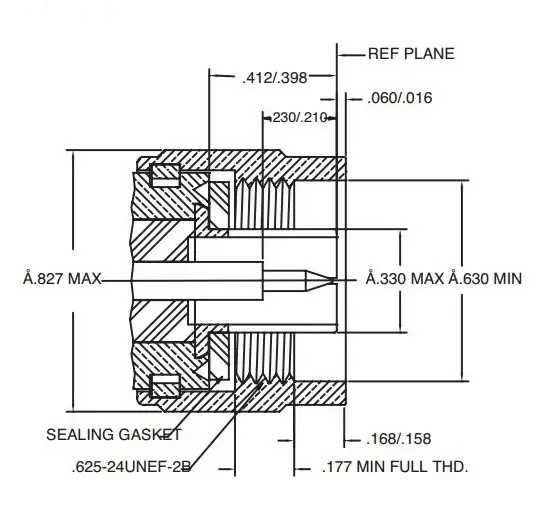
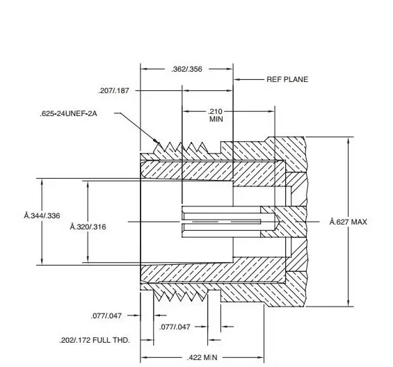
Interface Dimensions
Plug
Jack
Related Resources
.png)

.jpg)
.png)
.png)


Send us a Message
Please fill in the form below and we will contact you very soon.
Fields marked with an asterisk (*) are required.