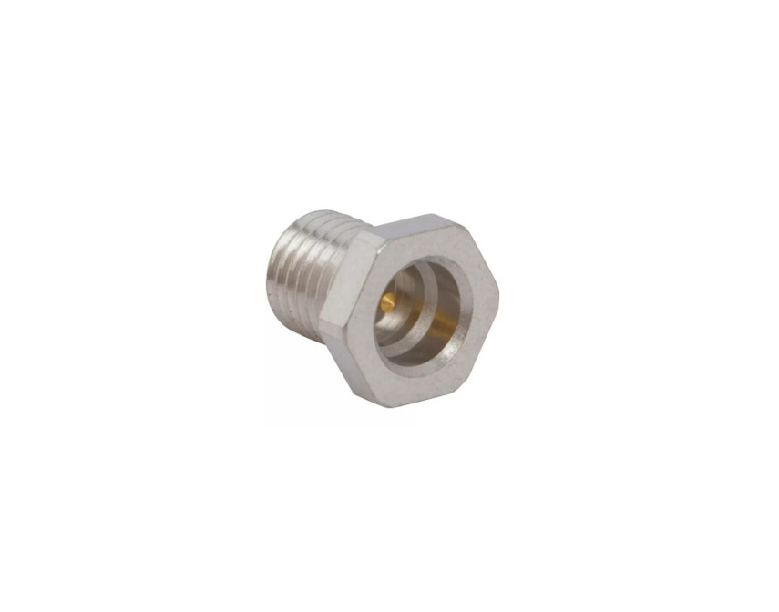
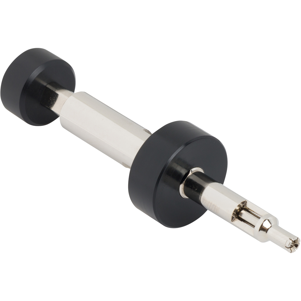
HD-EFI Connectors
Micro miniature 50 Ω board‑to‑board RF connectors with high float and blind‑mate capability
Overview
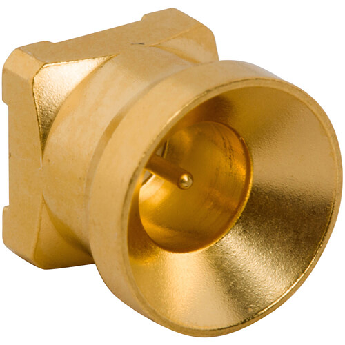
Amphenol RF’s HD‑EFI connectors are precision-engineered for compact, multi-layer PCB interconnections requiring alignment tolerance and high-frequency performance. Designed with generous axial and radial “float,” they support blind mating and accommodate board-to-board spacing variations—ideal for modular wireless systems and densely packed electronics.
With reliable RF performance up to 6 GHz and compact push-on contact geometry, HD‑EFI ensures stable signal integrity across multiple mating cycles. Available in common PCB jack and cable plug formats, plus bullet adapters for flexible board stack-ups, this series is perfect for broadband routers, military/aerospace gear, and telecom infrastructure.
Features and Benefits
- High float tolerance: ±0.7 mm axial and ±0.3 mm radial misalignment support error-prone assembly conditions.
- Blind-mate capability with crash-proof, closed-entry design protects contacts during mating.
- Compact and modular: micro-miniature interface supports multiple RF lines on small PCB real estate.
- 50 Ω performance to 6 GHz ensures broadband communication quality.
- Variety of formats: PCB jacks, cable plugs, and bullet adapters for stack flexibility.
Key Technical Details
- Impedance: 50 Ω nominal (broadband systems)
- Frequency Range: DC–6 GHz, with consistent performance across blind-mate range
- Voltage Rating: 335 VRMS continuous, up to 1 000 VRMS dielectric withstand
- Coupling Mechanism: push-on blind-mate, crash-resistant contacts
- Mechanical Float: ±0.7 mm axial / ±0.3 mm radial to handle PCB variances
Applications
- Modular telecom and broadband routers
- Military and aerospace communication modules
- Multi-network PCB stacks in instrumentation and medical systems
- Vehicle and defense wireless board-to-board assemblies
- Compact RF systems with strict alignment tolerances
Browse our HD‑EFI series including surface-mount PCB jacks, right-angle cable plugs, and an assortment of bullet adapters for precise stack-up configurations. For custom board spacing tolerances, cable-to-board transitions, or tailored integrated solutions, contact our engineering team to design a fit-for-purpose interface.
Specifications
HD-EFI Connectors
Electrical
| Impedance | 50 Ohm |
| Frequency Range | DC - 6 GHz |
| Voltage Rating | 335 Volts RMS Continuous |
| Dielectric Withstanding Voltage | 1000 Volts RMS Max |
| VSWR (Return Loss) |
|
|
Axial Misalignment ± 0.7 mm
|
|
|
DC - 2 GHz
|
1.14 (-24 dB) Max |
|
2 - 4 GHz
|
1.22 (-20 dB) Max |
|
4 - 6 GHz
|
1.38 (-16 dB) Max |
|
Axial Misalignment ± 0.3 mm
|
|
|
DC - 2 GHz
|
1.08 (-28 dB) Max |
|
2 - 4 GHz
|
1.12 (-25 dB) Max |
|
4 - 6 GHz
|
1.2 (-21 dB) Max |
| Insulation Resistance | 5000 MΩ Min |
| Center Contact Resistance | 5 mΩ Max |
| Outer Contact Resistance | 5 mΩ Max |
| Insertion Loss |
|
|
DC - 3 GHz
|
-0.14 dB Max |
|
3 - 6 GHz
|
-0.27 dB Max |
| 3rd Order Intermodulation | 930 & 955 MHz (2X43 dBm), -163dBc Max (Low PIM Designs) |
| Power Handling | 40 W Max @ 2.6 GHz @ 95ºC |
|
|
120 W Max @ 2.5 GHz @ 95ºC |
Environmental
| Temperature Range | −45°C to +125°C |
| Thermal Shock | MIL-STD-202, Method 107, Condition B |
| Corrosion | MIL-STD-202, Method 101, Condition B - 5% Salt Spray |
| Vibration | MIL-STD-202, Method 204, Condition B |
| Mechanical Shock | MIL-STD-202, Method 213, Condition A - No Discontinuity Permitted |
| Humidity/Temperature Cycling | MIL-STD-202, Method 106, Condition A |
| Temperature Life | 250 Hours at 125° C, No Damage to Parts |
Mechanical
| Mating Cycles | 50 Min (Limited Detent), 200 Min (Smooth Bore) |
| Coupling Mechanism | Push-On |
| Interface Specification | Amphenol RF Proprietary |
| Engagement Force | 12 N Max (Smooth Bore), 25 N Max (Limited Detent) |
| Disengagement Force | 2 - 6 N (Smooth Bore), 9 N Min (Limited Detent) |
| Mechanical Misalignment |
|
|
Axial
|
±0.7 mm |
|
Radial
|
±0.7 mm |
|
Max Float Angle
|
5⁰ Surface Mount Parts, 3.5⁰ Through-hole Mount Parts |
|
Min Board to Board Distance
|
11.46 mm |
Note: These characteristics are typical and may not apply to all connectors.
Connector configurations may affect performance.
Related Resources


Send us a Message
Please fill in the form below and we will contact you very soon.
Fields marked with an asterisk (*) are required.