MCX Connectors
Compact snap-on RF connectors offering 12 GHz broadband performance enabling broadband applications
Overview
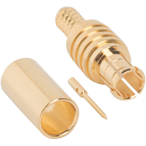
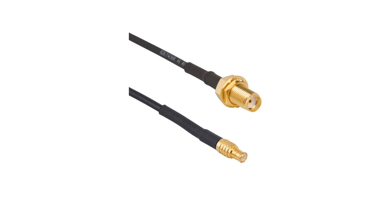
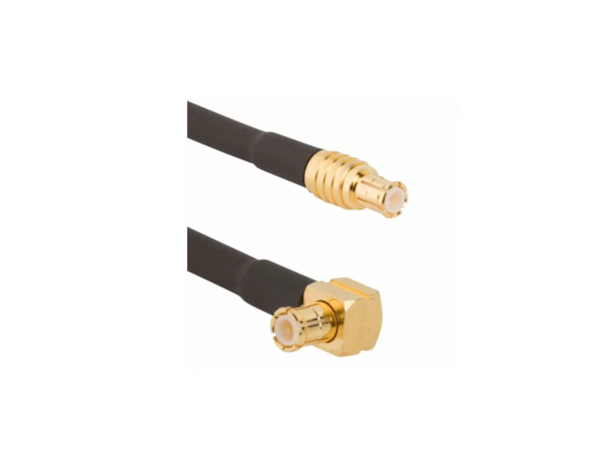
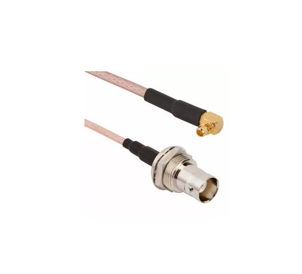
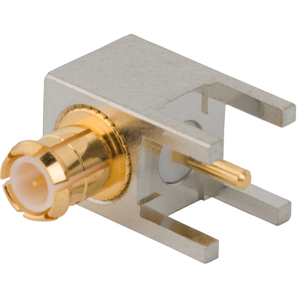
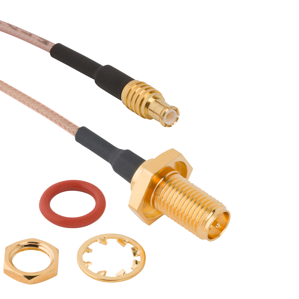
Amphenol RF’s MCX series delivers space-saving, push-on RF interconnects designed for quick assembly and dependable signal performance. Available in both 50 Ω and 75 Ω versions, MCX connectors support a range of applications, from wireless communications to automotive infotainment and instrumentation.
With operational bandwidth up to 12 GHz, strong mechanical durability, and a miniature form factor, MCX connectors provide engineers with reliable RF connections in tight spaces without compromising on performance.
Features and Benefits
- Broadband frequency support: Up to 12 GHz, ideal for RF, cellular, and video environments
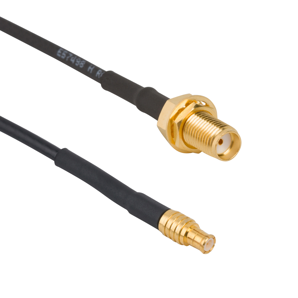
- Quick snap‑on coupling: Easy and repeatable mating without threaded hardware
- Versatile impedance options: Standard 50 Ω with select 75 Ω versions for video applications
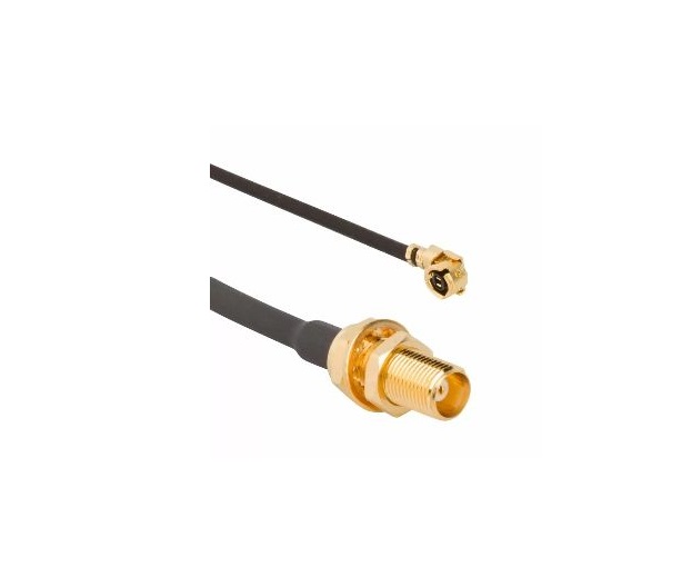
- Compact design: Suitable for dense PCB layouts and small cabling schemes
- High mating durability: Rated for 500+ cycles with consistent performance
Key Technical Details
- Impedance: 50 Ω nominal; available 75 Ω versions for specific video/frequency needs
- Frequency Range: DC–12 GHz (50 Ω); 75 Ω models support up to 6 GHz, with select parts rated for 12 GHz
- Voltage Rating: ~225 VRMS continuous (50 Ω); ~170 VRMS continuous (75 Ω); withstands higher dielectric voltages
- Mating Cycles: ≥ 500 cycles, ensuring longevity in frequent-use scenarios
- Temperature Range: –65 °C to +165 °C (may vary based on cable and configuration)
Applications
- Wireless antennas and RF modules
- GPS and navigation systems
- Laboratory and field test equipment
- Automotive infotainment and telematics
- Broadcast solutions and 12G video connectivity
Explore Amphenol RF’s MCX platform, featuring cable plugs, PCB jacks, bulkhead adapters, and sealed variants. For custom cable assemblies, impedance tuning, or ruggedized configurations, contact our engineering team to find the ideal MCX solution for your application.

Specifications
MCX Connectors
50 Ohm
Electrical
| Impedance | 50 Ohm |
| Frequency Range | DC - 6 GHz |
| Voltage Rating | 2255 Volts RMS Max Continuous |
| Dielectric Withstanding Voltage | 1000 VRMS Max |
| VSWR (Return Loss) | |
|
DC - 6 GHz
|
1.3 (-18 dB) Max |
| Insulation Resistance | 10000 MΩ Min |
| Center Contact Resistance | 5 mΩ Min |
| Outer Contact Resistance | 1 mΩ Min |
| RF Leakage | -60 dB Max @ 1 GHz |
| Insertion Loss | 0.10 db Max @ 1 GHz |
| Power Handling | 95 W Max @ 1 GHz @ 25 ºC |
Environmental
| Temperature Range | −65°C to +165°C |
| Thermal Shock | MIL-STD-202, Method 107 (Test Condition B), Except high temperatures @ +200⁰C |
| Corrosion | MIL-STD-202, Method 101 (Test Condition B) - 5% Salt Solution |
| Vibration | MIL-STD-202, Method 204, Snap-On (Test Condition B) |
| Mechanical Shock | MIL-STD-202, Method 213, Snap-On (Test Condition B) |
| Moisture Resistance | MIL-STD-202, Method 106 |
Mechanical
| Mating Cycles | 500 Min |
| Coupling Mechanism | Push-On |
| Interface Specification | CECC 22220 |
| Engagement Force | 20 N Max |
| Disengagement Force | 10 N Min |
75 Ohm
Electrical
| Impedance | 75 Ohm |
| Frequency Range | DC - 6 GHz (0 - 18 GHz on 12G Products) |
| Voltage Rating | 170 Volts RMS Max Continuous |
| Dielectric Withstanding Voltage | 500 VRMS Max |
| VSWR (Return Loss) | |
|
12G Products: DC - 6 GHz
|
1.22 (-20 dB) Max |
|
12G Products: 6 - 12 GHz
|
1.43 (-15 dB) Max |
| Insulation Resistance | 10000 MΩ Min |
| Center Contact Resistance | 5 mΩ Min |
| Outer Contact Resistance | 2.5 mΩ Min |
| RF Leakage | -60 dB Max @ 1 GHz |
| Insertion Loss | 0.10 db Max @ 1 GHz |
| Power Handling | 95 W Max @ 1 GHz @ 25 ºC |
Environmental
| Temperature Range | −65°C to +165°C |
| Thermal Shock | MIL-STD-202, Method 107 (Test Condition B), Except high temperatures @ +200⁰C |
| Corrosion | MIL-STD-202, Method 101 (Test Condition B) - 5% Salt Solution |
| Vibration | MIL-STD-202, Method 204, Snap-On (Test Condition B) |
| Mechanical Shock | MIL-STD-202, Method 213, Snap-On (Test Condition B) |
| Moisture Resistance | MIL-STD-202, Method 106 |
Mechanical
| Mating Cycles | 500 Min |
| Coupling Mechanism | Push-On |
| Interface Specification | CECC 22220 |
| Engagement Force | 10 N Max |
| Disengagement Force | 10 N Min |
Note: These characteristics are typical and may not apply to all connectors.
Connector configurations may affect performance.
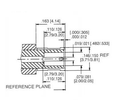
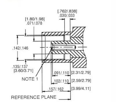
Interface Dimensions
Plug
Jack
Related Resources
.png)


Send us a Message
Please fill in the form below and we will contact you very soon.
Fields marked with an asterisk (*) are required.