N-Type Connectors
Reliable threaded RF connectors for rugged, high-frequency performance
Overview
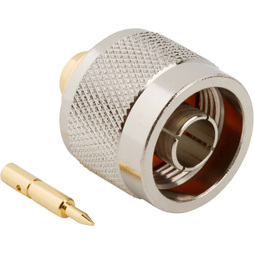
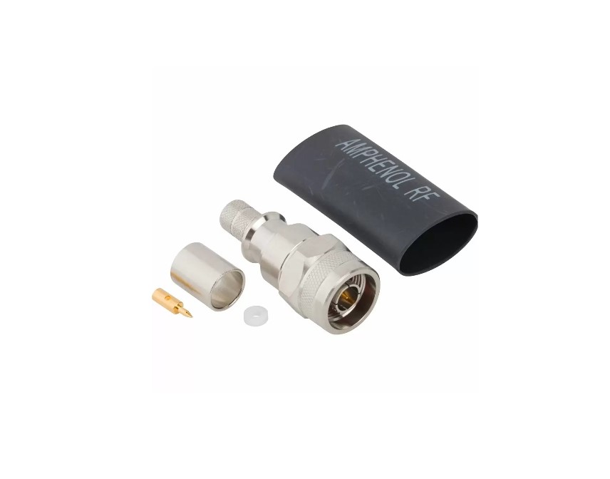
Amphenol RF’s N-Type connectors are rugged, weatherproof, medium-size RF interconnects designed for performance and durability in demanding environments. With threaded coupling and interchangeable compatibility to MIL‑C‑39012, they offer exceptional signal integrity up to 11 GHz—and even up to 18 GHz in extended-range models.
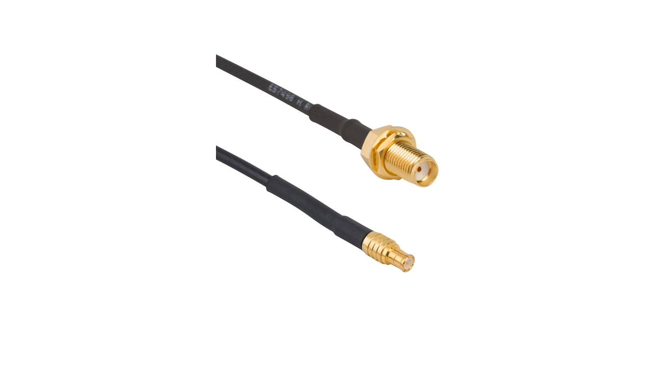
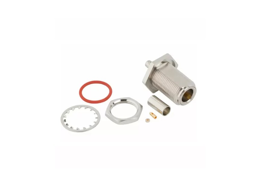
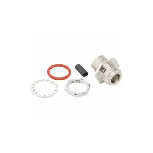
From classic base-station installations and radar systems to satellite communications and field instrumentation, our versatile N-Type line supports cable-mount, panel-mount, bulkhead, and right-angle configurations.
Features and Benefits
- Robust threaded 5/8‑24 coupling ensures stable connections under vibration
- High-frequency capability: standard models rated DC–11 GHz; extended versions up to 18 GHz
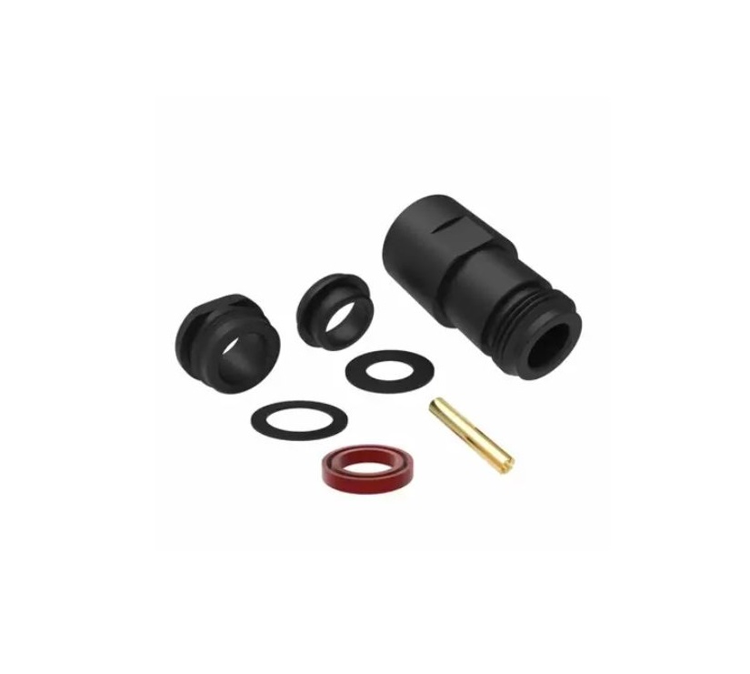
- Weatherproofed design suitable for outdoor and industrial use
- Broad cable compatibility: supports a range of coax sizes (e.g. RG‑213, LMR‑400, RG‑55, RG‑174)
- Broad product range: includes commercial, industrial, and MIL-grade plugs, jacks, and adapters
Key Technical Details
- Impedance: 50 Ω nominal
- Frequency Range: DC–11 GHz (standard); DC–18 GHz (extended-range)
- Voltage Rating: 500 VRMS continuous; dielectric withstand up to 1500 VRMS
- VSWR: Low reflection, tight control across frequency band
- Mating Cycles: ≥ 500 mating cycles typical, depending on connector style
- Temperature Range: –65 °C to +165 °C, depending on configuration and cable type
- Construction: Gold- or nickel-plated brass with PTFE insulators
- Sealed Options: Select models rated IP67 for outdoor use (e.g., field-installable LMR®‑400 plug)
Applications
- Cellular base stations and wireless infrastructure
- Satellite communications, radar, and military systems
- Broadcast and video distribution setups
- RF test and instrumentation assemblies
- Defense and industrial data links
Explore our complete N-Type portfolio—cable plugs, PCB and panel jacks, right-angle variants, bulkhead and field-installable designs, plus cross-series adapters connecting to SMA, TNC, F-Type, and others. If your design requires custom cable assemblies, harsh-environment ruggedization or precision test performance, contact our RF engineering experts for tailored solutions.
Specifications
N-Type Connectors
Electrical
| Impedance | 50 Ohm |
| Frequency Range | DC - 11 GHz (DC - 18 GHz on Extended Range Designs) |
| Voltage Rating | 500 Volts RMS Continuous |
| Dielectric Withstanding Voltage | 1500 VRMS Max |
| VSWR (Return Loss) | |
|
M39012 Straight Connectors
|
|
|
DC - 11 GHz
|
1.30 (-18 dB) Max |
|
M39012 Right Angle Connectors
|
|
|
DC - 9 GHz
|
1.35 (-16 dB) Max |
|
9 - 11 GHz
|
1.5 (-14 dB) Max |
| Insulation Resistance | 5000 MΩ Min |
| Center Contact Resistance | 1 mΩ Max |
| Outer Contact Resistance | 4 mΩ Max |
| RF Leakage | -90 dB Max (DC - 3 GHz) |
| Insertion Loss | |
|
M39012 Straight Connectors
|
0.15 dB Max (DC - 9 GHz) |
|
M39012 Right Angle Connectors
|
0.30 dB Max (DC - 10 GHz) |
| Passive Intermodulation (PIM) | -166 dBc with 2 X 43 dBm inputs |
| Power Handling | 300 W @ 10 GHz @ 25ºC |
Environmental
| Temperature Range | |
|
Typical
|
−65°C to +165°C |
|
Styrene Insulator or Phosphor Bronze Contact
|
−40°C to +85°C |
| Thermal Shock | MIL-STD-202, Method 107 (Test Condition B) except high temp rest @ +200⁰C |
| Corrosion | MIL-STD-202, Method 101 (Test Condition B) - 5% Salt Solution |
| Vibration | MIL-STD-202, Method 204 (Test Condition B) |
| Mechanical Shock | MMIL-STD-202, Method 213 (Test Condition I) - No Discontinutiy Permitted |
| Moisture Resistance | MIL-STD-202, Method 106 |
| Altitude | MIL-STD-202 Method 105 (Test Condition C) |
Mechanical
| Mating Cycles | 500 Min |
| Coupling Mechanism | Threaded |
| Interface Specification | MIL-STD-348 |
| Coupling Mechanism Retention Force | 100 lbs Min |
| Mating Torque, Min Working | 8-12 inch-pounds |
Note: These characteristics are typical and may not apply to all connectors.
Connector configurations may affect performance.
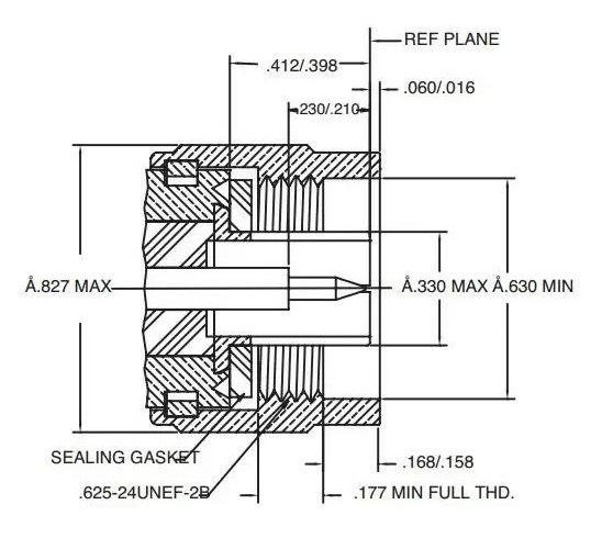
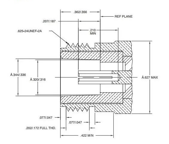
Interface Dimensions
Plug
Jack
Related Resources
.png)

.jpg)
.png)
.png)


Send us a Message
Please fill in the form below and we will contact you very soon.
Fields marked with an asterisk (*) are required.